

1. xerox 560 computer system - The UK Mirror Service
1. xerox 560 computer system - The UK Mirror Service
1. xerox 560 computer system - The UK Mirror Service

Create successful ePaper yourself
Turn your PDF publications into a flip-book with our unique Google optimized e-Paper software.
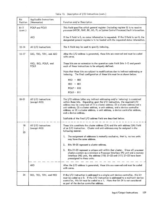
Table 13.Description of I/o Instructions (cont.)BitPositionApplicable Instructions(Mnemonics)Function and/or Description8-11 POLP and POLR(cont. )This field specifies which general register (including register 0) is to receiveprocessor(MIOP, RMP, BP, MI, PI, or System Control Processor) fault information.AIOIf the R field is 0, no status information is requested. If the R field is not 0, thedesignated general register is to be loaded with the requested status information.12-14All I/O instructions<strong>The</strong> X field may be used to specify indexing.15-17510, TIO, TDY, and AlOAfter the I/O address is generated, these bits are reserved and must be codedwith zeros.HIO, RIO, POLP, andPOLR<strong>The</strong>se bits are an extension to the operation code field (bits 1-7) and permiteach of these instructions to be uniquely defined.Note that these bits are subject to modifications due to indirect addressing orindexing. <strong>The</strong> final configuration of these bits must be as shown below:HIO = 000RIO = 001POLP = 010POLR = 01118-31All I/o instructions(except AIO)<strong>The</strong> I/O address (after any indirect addressing and/or indexing) is containedwithin these bits. Depending upon the I/O instruction, the required I/oaddress may be comprised of (1) a cluster address; (2) a cluster address and auni t addressi (3) a cluster address, a uni t address, and a devi ce controll eraddressi or (4) a cluster address, a unit address, a device controller address,and a device address.Subfields of the final I/o address field are described below.----- - -------- - - - - -1-- - - - - - - - - - - - - - - - - - - - - - - - - - --1823All I/o instructions(except Ala)<strong>The</strong>se bits constitute the cluster address (CA) and the unit address (UA) fieldof an I/O instruction. Cluster and unit addresses may be assigned in thefollowing manner:<strong>1.</strong> <strong>The</strong> assignment of addresses is mutually exclusive, that is, no two unitsmay have the same address.2. Bits 18-20 represent a cluster address.3. Bits 21-23 represent a unique unit within that cluster. Since all processorclusters contain as a minimum a Processor Interface (PI) unit and a memoryinterface (MI) unit, the address (110) 21-23 and (111) 21-23 have beenpreassigned to these units.- - - - - - -- - - - - - - - - - - - - - - - - - - -AlOAfter the I/o address is generated, these bits are reserved and must be codedwith zeros.24510, TIO, TDY , and HIOIf the I/O instruction is addressed to a single-unit device controller, this bitmust be coded as a O. If the I/O instruction is addressed to a multiunit devicecontroller, this bit must be coded as a <strong>1.</strong> Note that bit 24 is not consideredas part of the device controller address.Input/Output Instructions 129


