

1. xerox 560 computer system - The UK Mirror Service
1. xerox 560 computer system - The UK Mirror Service
1. xerox 560 computer system - The UK Mirror Service

You also want an ePaper? Increase the reach of your titles
YUMPU automatically turns print PDFs into web optimized ePapers that Google loves.
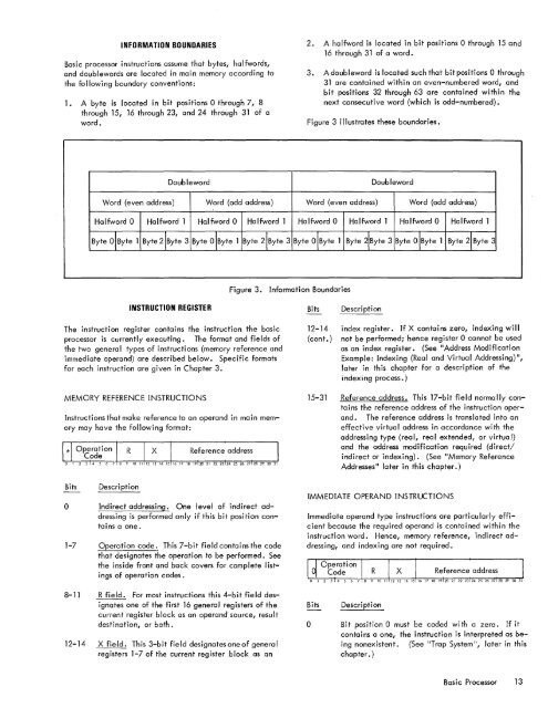
INFORMATION BOUNDARIESBasic processor instructions assume that bytes, halfwords,and doublewords are located in main memory according tothe following boundary conventions:<strong>1.</strong> A byte is located in bit positions 0 through 7, 8through 15, 16 through 23, and 24 through 31 of aword.2. A halfword is located in bit positions 0 through 15 and16 through 31 of a word.3. A doubleword is located such that bit positions 0 through31 are contained within an even-numbered word, andbit positions 32 through 63 are contained within thenext consecutive word (which is odd-numbered).Figure 3 illustrates these boundaries.DoublewordDoublewordWord (even address)Word (odd address)Word (even address)Word (odd address)Halfword 0 Halfword 1 Halfword 0 Halfword 1Halfword 0 Halfword 1 Halfword 0 Halfword 1Byte O! Byte 1 Byte 2!Byte 3 Byte 0 !Byte 1 Byte 2!Byte 3 Byte O! Byte 1 Byte 2!Byte 3 Byte 0 !Byte 1 Byte 2!Byte 3Figure 3. Information BoundariesINSTRUCTION REGISTERBitsDescription<strong>The</strong> instruction register contains the instruction the basicprocessor is currently executing. <strong>The</strong> format and fields ofthe two general types of instructions (memory reference andimmediate operand) are described below. Specific formatsfor each instruction are given in Chapter 3.MEMORY REFERENCE INSTRUCTIONSInstructions that make reference to an operand in main memorymay have the following format:12-14 index register. If X contains zero, indexing will(cont.) not be performed; hence register 0 cannot be usedas an index register. (See "Address ModificationExample: Indexing (Real and Virtual Addressing) ",later in this chapter for a description of theindexing process.)15-31 Reference address. Th i s 17 -b i t fi e I d norma II y containsthe reference address of the instruction operand.<strong>The</strong> reference address is translated into aneffective virtual address in accordance with theaddressing type (real, real extended, or virtual)and the address modification required (direct!indirect or indexing). (See "Memory ReferenceAddresses" later in this chapter.)Bitso1-7DescriptionIndirect addressing. One level of indirect addressingis performed only if this bit position containsa one.Operation code. This 7-bit field contains the codethat designates the operation to be performed. Seethe inside front and back covers for complete listingsof operation codes.IMMEDIATE OPERAND INSTRUCTIONSImmediate operand type instructions are particularly efficientbecause the required operand is contained within theinstruction word. Hence, memory reference, indirect addressing,and indexing are not required.8-11 R field. For most instructions this 4-bit field designatesone of the first 16 general registers of thecurrent register block as an operand source, resultdestination, or both.12-14 X field. This 3-bit field designates one of generalregisters 1-7 of the current register block as anBitsoDescriptionBit position 0 must be coded with a zero. If itcontains a one, the instruction is interpreted as beingnonexistent. (See "Trap System ", later in thischapter. )Bas i c Processor 13


