

1. xerox 560 computer system - The UK Mirror Service
1. xerox 560 computer system - The UK Mirror Service
1. xerox 560 computer system - The UK Mirror Service

You also want an ePaper? Increase the reach of your titles
YUMPU automatically turns print PDFs into web optimized ePapers that Google loves.
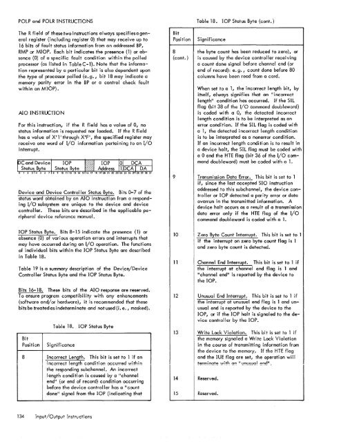
POLP and POLR INSTRUCTIONS<strong>The</strong> R field of these two instructions always specifiesa generalregister (including register 0) that may receive up to16 bits of fault status information from an addressed BP,RMP or MIOP. Each bit indicates the presence (l) or absence(O) of a specific fault condition within the polledprocessor (as listed in Table C-1). Note that the informationrepresented by a particular bit is also dependent uponthe type of processor polled (e. g., bit 18 may indicate amemory parity error in the BP or a control check faultwithin an MIOP).AlO INSTRUCTIONFor this instruction, if the R field has a value of 0, nostatus information is requested nor loaded. If the R fieldhas a value of X'l' through X'F', the specified register mayreceive one word of I/o information pertaining to an I/Ointerrupt.BitPositionTable 18. lOP Status Byte (cont.)Significance8 the byte count has been reduced to zero), or(cont.) is caused by the device controller receivinga count done signal before channel end (orend of record): e. g., count done before 80columns have been read from a card.When set to a I, the incorrect length bit, byitself, always signifies that an "incorrectlength" condition has occurred. If the SILflag (bit 38 of the I/O command doubleword)is coded with a 0, the detected incorrectlength condition is to be interpreted as anerror condition. If the SIL flag is coded witha 1, the detected incorrect length conditionis to be interpreted as anonerror condition.If an incorrect length condition is to result ina device halt, the SIL flag must be coded witha 0 and the HTE flag (bit 36 of the I/O commanddoubleword) must be coded with a <strong>1.</strong>Device and Device Controller Status Byte. Bits 0-7 of thestatus word obtained by an AIO instruction from a respondingI/o sub<strong>system</strong> are unique to the device and devicecontroller. <strong>The</strong>se bits are described in the applicable peripheraldevice reference 'manual.9Transmission Data Error. This bit is set to 1if, since the last accepted SIO instructionaddressed to this subchannel, the device controlleror lOP detected a parity error or dataoverrun in the transmitted information. Adevice halt occurs as a result of a transmissiondata error only if the HTE flag of the I/Ocommand doubleword is coded with a <strong>1.</strong>lOP Status Byte. Bits 8-15 indicate the presence (1) orabsence (0) of various operation errors and interrupts thatmay have occurred during an I/O operation. <strong>The</strong> functionsof individual bits within the lOP Status Byte are describedin Table 18.Table 19 is a summary description of the Device/DeviceController Status Byte and the lOP Status Byte.Bits 16-18. <strong>The</strong>se bits of the AIO response are reserved.To ensure program compatibility with any enhancements(software and/or hardware), it is recommended that thesebits be treated as indeterminate and not used (i. e., masked).BitPositionTable 18. lOP Status ByteSignificance8 Incorrect Length. This bit is set to 1 if anincorrect length condition occurred withinthe responding subchannel. An incorrectlength condition is caused by a IIchannelend" (or end of record) condition occurringbefore the device controller has a "countdone" signal from the lOP (indicating that101112Zero Byte Count Interrupt. This bit is set to 1if the interrupt on zero byte count flag is 1and zero byte count is detected.Channel End Interrupt. This bit is set to 1 ifthe interrupt at channel end flag is 1 andIIchannel end ll is reported by the device tothe lOP.Unusual End Interrupt. This bit is set to 1 ifthe interrupt at unusual end flag is 1 and unusualend is reported by the device to thelOP, or if the lOP halt is signaled to the devicecontroller by the lOP.13 Write Lock Violation. This bit is set to 1 ifthe memory signaled a Write Lock Violationin the course of transmitting information fromthe device to the memory. If the HTE flagand the IUE flag are set, the operati on wi III terminate with an "l-'n'-'5'-'0! end".14 Reserved.15 Reserved.134 Input/Output Instructions


