4. INPUT jOUTPUT OPERATIONSTo accommodate the variety and number of I/o devi ceswhich may be required for scientific and commercial applications,a Xerox <strong>560</strong> <strong>computer</strong> <strong>system</strong> may include the following:External Direct Input/Output (DIO) interface,Multiplexor Input/Output Processors (MIOPs), and RotatingMemory Processors (RMPs).more of the following types of device controllers may beconnected to an MIOP:<strong>1.</strong> Single-unit device controller {internal or external}.2. Multi-unit device controller {internal or external}."3. Unit-record controller {internal or external}.EXTERNAL DlO INTERFACEAn external DIO interface permits standard and speciallydesigned I/O devices to perform I/O operations (normallyin a real-time environment) that are controlled directly bythe basic processor (BP). Appropriate control signals andup to one word {32 bi ts} of data may be exchanged betweenthe BP and an addressed I/O device for each READ DIRECTor WRITE DIRECT instruction executed by the BP.During a WRITE DIRECT instruction (Mode 2 through F),the BP holds the control and data-lines stable until anacknowledgment signal is received from the addressed I/Odevice. During a READ DIRECT instruction (Mode 2through F), the BP holds the control lines stable until theaddressed I/o device furnishes the data accompanied withan acknowledgment signa/. Any delay encountered inreceiving the acknowledgment signal, for either READDIRECT or WRITE DIRECT instructions, does not have anadverse effect upon I/O operations being performed bythe MIOP or RMP <strong>system</strong>s.Refer to Xerox publication 90 09 73 {Interface DesignManual} for further detai Is pertaining to the external DIOinterface. Also, refer to appropriate peripheral referencemanuals for details on control and data signals.MULTIPLEXOR INPUT/OUTPUT PROCESSOR (MIOP)An MIOP permits standard and commercially available I/Odevices (e. g., card readers, card punches, magnetic tapeunits, etc.) to be controlled primari Iy by individual I/Osubchannels within the MIOP and associated device controllers.Depending upon the number of I/o subchannelsassigned (maximum of 16, as described under II Device Controllers"),an equivalent number of I/O operations may beperformed si mu I taneously.Generally, an internal device controller is physically connectedvia the internal I/o interface.An external device controller is located remotely to theMIOP and may require one or more separate chassis to accommodateit.A single-unit device controller {internal or external} isspecifically designed to control only one I/o device,usually a unit-record device such as a card reader, a cardpunch, or a line printer. Characteristics of a single-unitdevice controller are dependent upon the device controlled.(Refer to an appropriate peripheral reference manual forfurther information. )A multi -unit device controller (internal or external) isspecially designed to control more than one I/o device,where all the I/O devices are of the same type {e. g.,magnetic tape units or RADs}. However, only one I/odevice at a time may be actively involved in a data transferoperation. Characteristics of a multi-unit device controllerare dependent upon the I/O devices controlled. Forexample, a multi -unit device controller for magnetic tapeunits may control up to eight units. (Refer to an appropriateperipheral reference manual for further information.)Unit-record controllers {internal or external} are designedto control up to eight unit record type of I/O devi ces (e. g. ,card readers; card PlJnches; line printers). AI! I/o devicesattached to a unit-record controller need not be ofthe same type. All I/o devices attached to a unit-recordcontroller may perform separate I/O operations, includingdata transfers, si mu I taneously.<strong>The</strong> number of device controllers, as well as the number ofI/O devices, that may be connected to an MIOP is dependentupon the following considerations:<strong>1.</strong> <strong>The</strong> maximum number of I/O subchannels within anMIOP is 16.DEVICE CONTROLLERSAll I/O devices associated with an MIOP are connectedvia an appropriate device controller. Depending upon thenumber and type of I/o devices to be connected, one or2. Each single-unit device controller {internal or external}requires one I/o subchannel.3. Each multi-unit device controller (internal or external)requires one of the first eight subchannels withinthe MIOP.142 Input/Output Operati ons
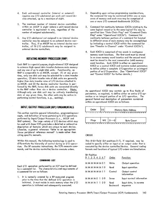
4. Each unit-record controller (internal or external)requires one I/O subchannel per each unit record deviceattached, up to a maximum of eight.5. <strong>The</strong> maximum number of internal device controllerswithin an MIOP is eight (where a unit-record devicecontroller is equivalent to one, regardless of thenumber of assigned subchannels).6. Any I/O subchannel not assigned to an internal devicecontroller may be assigned to an external device controller.Thus, if an MIOP has no internal device controller,all 16 I/O subchannels may be assigned toexternal device controllers.ROTATING MEMORY PROCESSOR (RMP)Each RMP is a speci_al purpose, single-channel lOP designedto enhance high-speed data transfers between main memoryand anyone of up to eight disk units. Functionally, anRMP is comparable to an MIOP, except: (1) at any giventime, only one disk unit may be selected for a data transferoperation, . (2) data transfer rate of disk units are generallyhigher than data transfer rates of I/O devices attached toan MIOP, and (3) the device controller function is performedby the RMP, hence disk units are connected directlyto the RMP rather than via a device controller. (Note:Although only one disk unit may be actively transferdngdata at any given time, the other units may be active inperforming control functions, e. g., seeking).2. Depending upon various programming considerations,the command list may be contained within one or moreareas of memory and each area may be comprised ofone or more I/O command doublewords (IOCDs).3. Command list continuity between 10CDs relating to thesame logical record or to the same logical file may bespecified (see "Data Chain Flag" and "Command ChainFlag ll under II Operationa I 10CDs"). Command listcontinuity between portions of a command list locatedin different areas of main memory may be accomplishedby including a control 10CD within the command list(see "Transfer in Channel II under "Control 10CDs").4. Each 10CD is comprised of two words in contiguousmemory word locations. <strong>The</strong> first word must be storedin an even memory word location and the second wordmust be stored in the next consecutive (odd) memoryword location. Each IOCD is either an operationalIOCD or a control IOCD and contains coded parametersto define either a complete I/Ooperation or an integralportion of an I/Ooperation. (See "Operational IOCD"and IIControl IOCD" for further detai Is. )OPERATIONAL lOCOAn operational IOCD may contain up to five fields ofparameters, as required, to define either an entire I/o operationor an integral portion of an I/o operation._ <strong>The</strong>general format and description of parameters containedwithin an operational 10CD are as follows:iNPUT jOUTPUT PKOCESSOR liOfij FUNUAMENTAlSThis section contains general information, programming concepts,and definition of terms pertaining to I/O operationsperformed by Input/Output Processors (i. e., MIOP andRMP <strong>system</strong>s). <strong>The</strong> large variety of I/O devices which maybe used with these lOPs precludes a detailed or exhaustivedescription of features which are unique to each device.Likewise, a general reference "Refer to an appropriateXerox peripheral reference manual" is made rather thanciting specific manuals.Within this manual, the following terminology is used todifferentiate the hierarchy of control during an I/o operation:<strong>The</strong> BP executes instructions, the lOPs execute commands,and the device controller/device execute orders.COMMAND LISTEach I/O operation performed by an lOP must be definedby a command list. <strong>The</strong> characteristics and requirements ofa command list are as follows:<strong>1.</strong> It is normally created by a BP-executed programprior to the time that the defined I/o operation isinitiated. It must reside in main memory when the I/ooperation is initiated and subsequently executed.ORDERThis 8-bit field (bit positions 0-7), if required, may becoded to specify either an input or an output order that isexecuted by the device controller/device. General codingformats and functions of typical I/o orders are listed below:Bit Positiono 1 2 3 4 5 6 7 Order FunctionMMMMMM01MMMMMM10MMMMMM11MMMMOMMMM10000WriteReadControlSenseReadBackwardOutput operationInput operationOutput controlinformationInput control informationInput data, in reversesequenceRotating Memory Processor (RMP)/Input/Output Processor (lOP) Fundamentals 143
- Page 1 and 2:
Xerox 560 ComputerReference Manual9
- Page 5 and 6:
4. INPUT/OUTPUT OPERA TIO NS 142 AG
- Page 7 and 8:
1. XEROX 560 COMPUTER SYSTEMINTRODU
- Page 10 and 11:
Many operations are performed in fl
- Page 12 and 13:
Rapid Context Switching. When respo
- Page 14 and 15:
2. SYSTEM ORGANIZATIONThe elements
- Page 16:
FAST MEMORYARITHMETIC AND CONTROL U
- Page 19 and 20:
INFORMATION BOUNDARIESBasic process
- Page 21 and 22:
(Maximumof eight)Core Core Core Cor
- Page 23 and 24:
3. Diagnostic logic. Each memory dr
- Page 25 and 26:
eference address field of the instr
- Page 27 and 28:
Instruction in memory:Instruction i
- Page 29 and 30:
Real-extended addressing is specifi
- Page 31:
Table 1. Basic Processor Operating
- Page 35 and 36:
DesignationFunctionDesignationFunct
- Page 37 and 38:
InterruptStateDisarmedArmed[$Waitin
- Page 39 and 40:
AddressTable 2. Interrupt Locations
- Page 41 and 42:
is assumed to contain an XPSD or a
- Page 43 and 44:
Table 3. Summary of Trap LocationsL
- Page 45 and 46:
TRAP MASKSThe programmer may mask t
- Page 47 and 48:
PUSH-DOWN STACK LIMIT TRAPPush-down
- Page 49 and 50:
Instruction Name Mnemonic FaultDeci
- Page 51 and 52:
subroutine. However, with certain c
- Page 53 and 54:
3. INSTRUCTION REPERTOIREThis chapt
- Page 55 and 56:
CC1 is unchanged by the instruction
- Page 57 and 58:
Condition code settings:2 3 4 Resul
- Page 59 and 60:
Example 2, odd R field value:Before
- Page 61 and 62:
significance (FS), floating zero (F
- Page 63 and 64:
next sequential register after regi
- Page 65 and 66:
R 1 R2 R3 MeaningoThe effective vir
- Page 67 and 68:
Condition code settings:2 3 4 Resul
- Page 69 and 70:
MIMULTIPLY IMMEDIATE(Immediate oper
- Page 71 and 72:
original contents of register R, re
- Page 73 and 74:
Instruction NameCompare HalfwordMne
- Page 75 and 76:
Condition code settings:2 3 4 Resul
- Page 77 and 78:
2 3 4 Result of ShiftCircular Shift
- Page 79 and 80:
4. At the completion of the left sh
- Page 81 and 82:
Instruction NameFloating Subtract L
- Page 83 and 84:
The following table shows the possi
- Page 85 and 86:
Table 8.Condition Code Settings for
- Page 87 and 88:
PACKED DECIMAL NUMBERSAll decimal a
- Page 89 and 90:
DSTDECIMAL STORE(Byte index alignme
- Page 91 and 92:
If no indirect addressing or indexi
- Page 93 and 94:
Instruction NameMnemonicDesignation
- Page 95 and 96:
Both byte strings are C bytes in le
- Page 97 and 98: of the destination byte that caused
- Page 99 and 100: again present, unti I a positive or
- Page 101 and 102: The new contents of register 7 are:
- Page 103 and 104: traps to location X'42 1 as a resul
- Page 105 and 106: If there is sufficient space in the
- Page 107 and 108: If CC1, or CC3, or both CC1 and CC3
- Page 109 and 110: appropriate memory stack locations
- Page 111 and 112: II, EI) are generated by II ORing"
- Page 113 and 114: In the real extended addressing mod
- Page 115 and 116: CAll INSTRUCTIONSEach ofthe four CA
- Page 117 and 118: The XPSD instruction' is used for t
- Page 119 and 120: If (I)1O = 0, trap or interrupt ins
- Page 121 and 122: For either memory map format and ei
- Page 123 and 124: initial value plus the initial valu
- Page 125 and 126: Table 9. Status Word 0Field Bits Co
- Page 127 and 128: READ INTERRUPT INHIBITSThe followin
- Page 129 and 130: Table 11.Read Direct Mode 9 Status
- Page 131 and 132: SET ALARM INDICATORThe following co
- Page 133 and 134: INPUT jOUTPUT INSTRUCTIONSThe I/o i
- Page 135 and 136: Table 13.Description of I/o Instruc
- Page 137 and 138: Table 15.Device Status Byte (Regist
- Page 139 and 140: Table 16. Operational Status Byte (
- Page 141 and 142: Table 19.Status Response Bits for A
- Page 143 and 144: If CC4 = 0, the MIOP is in a normal
- Page 145 and 146: 2 3 4 Meaningo 0 I/o address not re
- Page 147: The functions of bits within the DC
- Page 151 and 152: Interrupt at Channel End (Bit Posit
- Page 153 and 154: Transfer in Channel. A control lOCO
- Page 155 and 156: Otherwise, the first word of the ne
- Page 157 and 158: Depending upon the characteristics
- Page 159 and 160: change the rate on the primary cons
- Page 161 and 162: Location(hex) (dec)20 3221 3322 342
- Page 163 and 164: Table 22.Diagnostic Control (P-Mode
- Page 165 and 166: at its normal rate (e. g., fixed du
- Page 167 and 168: SET LOW CLOCK MARGINSThis command c
- Page 169 and 170: BP STATUS AND NO.Th i s group of i
- Page 171 and 172: Input5MPri ntout5MFunctionStore X 1
- Page 173 and 174: 6. SYSTEM CONFIGURATION CONTROLPool
- Page 175 and 176: Table 25. Functions of Processor Cl
- Page 177: Table 26. Functions of Memory Unit
- Page 180 and 181: STANDARD 8-BIT COMPUTER CODES (EBCD
- Page 182 and 183: STANDARD SYMBOL-CODE CORRESPONDENCE
- Page 184 and 185: STANDARD SYMBOL-CODE CORRESPONDENCE
- Page 186 and 187: TABLE OF POWERS OF SIXTEEN II162564
- Page 188 and 189: HEXADECIMAL-DECIMAL INTEGER CONVERS
- Page 190 and 191: HEXADECIMAL-DECIMAL INTEGER CONVERS
- Page 192 and 193: HEXADECIMAL-DECIMAL INTEGER CONVERS
- Page 194 and 195: HEXADECIMAL-DECIMAL FRACTION CONVER
- Page 196 and 197: HEXADECIMAL-DECIMAL FRACTION CONVER
- Page 198 and 199:
APPENDIX B.GLOSSARY OF SYMBOLIC TER
- Page 200 and 201:
TermMeaningTermMeaningWKxWrite key
- Page 202 and 203:
Table C-2. Memory Unit Status Regis
- Page 204 and 205:
Y OYf'lV r'f'lrnf'lrtil"\n'''' ....
- Page 206:
701 South Aviation BoulevardEI Segu