

1. xerox 560 computer system - The UK Mirror Service
1. xerox 560 computer system - The UK Mirror Service
1. xerox 560 computer system - The UK Mirror Service

Create successful ePaper yourself
Turn your PDF publications into a flip-book with our unique Google optimized e-Paper software.
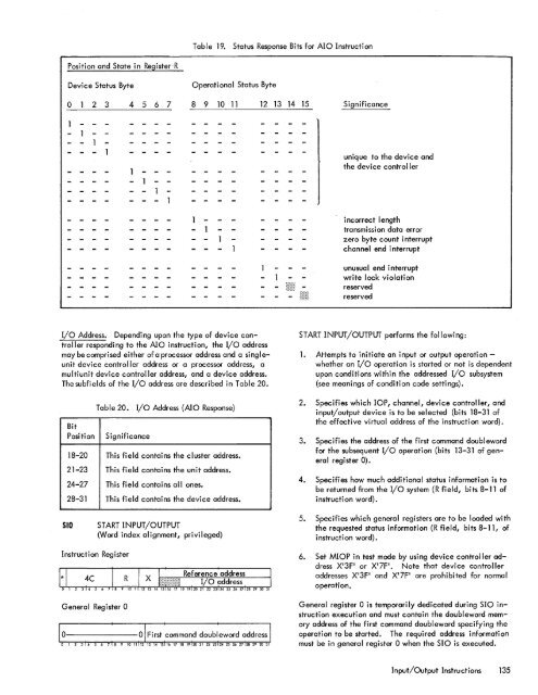
Table 19.Status Response Bits for AIO InstructionPosition and State in Register-RDevice Status ByteOperational Status Byteo 2 3 4 567 8 9 10 11 12 13 14 15 Significanceunique to the device andthe device controllerincorrect lengthtransmission data errorzero byte count interruptchannel end interruptunusual end interruptwrite lock violationreservedreservedI/O Address. Depending upon the type of device controllerresponding to the AIO instruction, the I/O addressmay be comprised either of a processor address and a singleunitdevice controller address or a processor address, amultiunit device controller address, and a device address.<strong>The</strong> subfields of the I/O address are described in Table 20.BitPositionTable 20. I/o Address (AIO Response)Significance18-20 This field contains the cluster address.21-23 This field contains the unit address.24-27 This field contains all ones.28-31 This field contains the device address.START INPUT/OUTPUT performs the following:<strong>1.</strong> Attempts to initiate an input or output operationwhetheran I/O operation is started or not is dependentupon conditions within the addressed I/o sub<strong>system</strong>(see meanings of condition code settings).2. Specifies which lOP, channel, device controller, andinput/output device is to be selected (bits 18-31 ofthe effective virtual address of the instruction word).3. Specifies the address of the first command doublewordfor the subsequent I/O operation (bits 13-31 of generalregister 0).4. Specifies how much additional status information is tobe returned from the I/O <strong>system</strong> (R field, bits 8-11 ofinstruction word).SIDSTART INPUT/OUTPUT(Word index alignment, privileged)5. Specifies which general registers are to be loaded withthe requested status information (R field, bits 8-11, ofinstruction word).Instruction RegisterGeneral Register 06. Set MIOP in test mode by using device controller addressX'3P or X'7F'. Note that device controlleraddresses X'3F' and X'7F' are prohibited for normaloperation.General register 0 is temporari Iy dedicated during SIO instructionexecution and must contain the doubleword memoryaddress of the first command doubleword specifying theoperation to be started. <strong>The</strong> required address informationmust be in general register 0 when the SIO is executed.Input/Output Instructions 135


