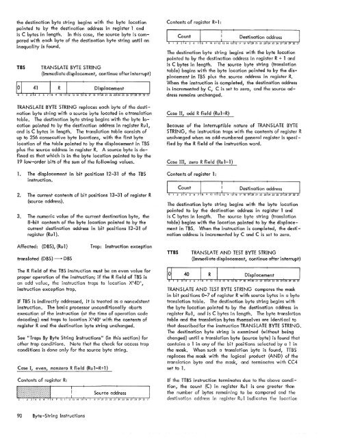
the destination byte string begins with the byte locationpointed to by the destination address in register 1 andis C bytes in length. In this case, the source byte is comparedwith each byte of the destination byte string unti I aninequality is found.TBSTRANSLATE BYTE STRING(Immediate displacement, continue after interrupt)TRANSLATE BYTE STRING replaces each byte of the destinationbyte string with a source byte located in a translationtable. <strong>The</strong> destination byte string begins with the byte locationpointed to by the destination address in regi ster Ru 1,and is C bytes in length. <strong>The</strong> translation table consists ofup to 256 consecutive byte locations, with the first bytelocation of the table pointed to by the displacement in TBSplus the source address in register R. A source byte is definedas that which is in the byte location pointed to by the19 low-order bits of the sum of the following values.<strong>1.</strong> <strong>The</strong> displacement in bit positions 12-31 of the TBSinstruction.Contents of register R+l:<strong>The</strong> destination byte string begins with the byte locationpointed to by the destination address in register R + 1 andis C bytes in length. <strong>The</strong> source byte string {translationtable} begins with the byte location pointed to by the displacementin TBS plus the. source address in register R.When the instruction is completed, the destination addressis incremented by C, C is set to zero, and the source addressremains unchanged.Case II, odd R fi e Id {Ru 1 =R}Because of the interruptible nature of TRANSLATE BYTESTRING, the instruction traps with the contents of register Runchanged when an odd-numbered general register is specifiedby the R field of the instruction word.Case III, zero R field {Ru1=1}Contents of register 1:2. <strong>The</strong> current contents of bit positions 13-31 of register R{source address}.3. <strong>The</strong> numeric value of the current destination byte, the8-bit contents of the byte location pointed to by thecurrent destination address in bit positions 13-31 ofregister {Ru 1}.<strong>The</strong> destination byte string begins with the byte locationpointed to by the destination address in register 1 andis C bytes in length. <strong>The</strong> source byte string {translationtable} begins with the location pointed to by the displacementin TBS. When the instruction is completed, the destinationaddress is incremented by C and C is set to zero.Affected: (DBS), {Ru 1}translated (DBS) -DBSTrap: Instruction exceptionTTBSTRANSLATE AND TEST BYTE STRING{Immediate displacement, continue after interrupt}<strong>The</strong> R field of the TBS instruction must be an even value forproper operation of the instruction; if the R field of TBS isen odd value, the instruction traps to location X'4D',instruction exception trap.If TBS is indirectly addressed, it is treated as a nonexistentinstruction. <strong>The</strong> basic processor unconditionally abortsexecution of the instruction (at the time of operation codedecoding) and traps to location X'40' with the contents ofregister R and the destination byte string unchanged.See IITraps By Byte String Instructions" (in this section) forother trap conditions. Note that the check for access trapconditions is done only for the source byte string.Case I, even, nonzero R field (Ru1=R+l)Contents of register R:TRANSLATE AND TEST BYTE STRING compares the maskin bit positions 0-7 of register R with source bytes in a bytetranslation table. <strong>The</strong> destination byte string begins withthe byte location pointed to by the destination address inregister Rul, and is C bytes in length. <strong>The</strong> byte translationtable and the translation bytes themselves are identi cal tothat described for the instruction TRANSLATE BYTE STRING.<strong>The</strong> destination byte string is examined (without beingchanged) unti I a translation byte {source byte} is found thatcontains a 1 in any of the bit positions selected by a 1 inthe mask. When such a translation byte is found, TTBSreplaces the mask with the logical product (AND) of thetransiation byte and the mask, and terminates with CC4set to <strong>1.</strong>If the TTBS instruction terminates due to the above condition,the count (C) in register Rul is one greater thanthe number of bytes remaining to be compared and thedestination address in register Rul indicates the location90 Byte-String Instructions
of the destination byte that caused the instruction toterminate. If no translation byte is found that satisfiesthe above condition after the specified number of destinationbytes have been compared, TTBS terminates with CC4reset to O. In no case does the TTBS instruction changethe source byte stri ng.Case II, odd R fieldBecause of the interruptible nature of TRANS LATE ANDTEST BYTE STRING the instruction traps with the contentsof register R unchanged when an odd-numbered general registeris specified by the R field of the instruction word.Affected: (R), (Rul), CC4Trap: Instruction exceptionIf translated (SBS) n mask I 0, translated (SBS) n maskmaskand stopIf translated (SBS) n mask = 0, continueCase III, zero R field (Rul=1)Contents of register 1:Condition code settings:2 3 4 Result of TTBS- 0 Translation bytes and the mask do not compareones any place.<strong>The</strong> last translation byte compared with themask contained at least one 1 correspondingto a 1 in the mask.<strong>The</strong> destination byte string begins with the byte locationpointed to by the destination address in register 1 and isC bytes in length. <strong>The</strong> source byte string (translation table)begins with the location pointed to by the displacement inTTBS. In this case, the instruction automatically providesa mask of eight lis. (This is an exception to the generalrule, used in the other byte-string instructions, the register0 provides all OIS as its contents. )<strong>The</strong> R field of the TTBS instruction must be an even valuefor proper operation of the instruction; if the R field of TTBSis an odd value, the instruction traps to location X l 4D I ,instruction exception trap.If TTBS is indirectly addressed, it is treated as a nonexistentInsrrucrion. <strong>The</strong> basic processor unconciiTionaiiy abortsexecution of the instruction (at the time of operation codedecoding) and traps to location X I 40 1 with the contents ofregister R and the destination byte string unchanged.See IITraps By Byte String Instructions" (in this section) forother trap conditions. Note that the check for access trapconditions is done only for the source byte string.Case I, even, nonzero R field (Rul=R+1)Contents of register R:Contents of register R+l:Count I !: Destination ~ddress Io 1 2 314 5 6 7 8 9 10 11112 13 14 15 16 17 18 19120 212223;2425262712829 30 31<strong>The</strong> destination byte string begins with the byte locationpointed to by the destination address in register R + 1 andis C bytes in length. <strong>The</strong> source byte string (translationtable) begins with the byte location pointed to by the displacementin TTBS plus the source address in register R.EBSo 1 2EDIT BYTE STRING(Immedi ate displacement, continue after interrupt)63 I R I : DisPlacem~nt I7 8 9 10 11 12 13 14 15 16 17 18 19120 21 22 23 24 25 26 27128 29 30 31EDIT BYTE STRING converts a decimal information fieldfrom packed decimal format to zoned decimal EBCDIC format,under control of the editing pattern in the destinationbyte string, and replaces the destination byte string with theedited, zoned result. (See "Decimal Instructions", "PackedDecimal Numbers", and "Zoned Decimal Numbers" fora description of packed and zoned decimal formats.) EBSproceeds one byte at a time, starting with the first (mostsignificant) byte of the editing pattern, and continuesunti I all bytes in the editing pattern have been processed.<strong>The</strong> fill character, contained in bit position 0-7 of registerR, replaces the pattern byte under specifi ed conditions.More than one decimal number field can be edited by asingle EBS instruction if the pattern in memory is, in fact,a series of patterns corresponding to a series of numberfields. In such cases, however, after the EBS instruction iscompleted, the condition code indicates the result of thelast decimal number field processed and register 1 containsthe byte address (or the byte address plus 1) of the last significanceindicator in the edited destination byte string.(This allows the insertion of a floating dollar sign, etc.,with a subsequent instruction. )R must be an even value (excluding 0) for proper operationof the instruction; if R is an odd value or equal to zero, thebasic processor traps to location X I 4D I , instruction exceptiontrap, with the contents in register R unchanged.Byte-String Instructions 91
- Page 1 and 2:
Xerox 560 ComputerReference Manual9
- Page 5 and 6:
4. INPUT/OUTPUT OPERA TIO NS 142 AG
- Page 7 and 8:
1. XEROX 560 COMPUTER SYSTEMINTRODU
- Page 10 and 11:
Many operations are performed in fl
- Page 12 and 13:
Rapid Context Switching. When respo
- Page 14 and 15:
2. SYSTEM ORGANIZATIONThe elements
- Page 16:
FAST MEMORYARITHMETIC AND CONTROL U
- Page 19 and 20:
INFORMATION BOUNDARIESBasic process
- Page 21 and 22:
(Maximumof eight)Core Core Core Cor
- Page 23 and 24:
3. Diagnostic logic. Each memory dr
- Page 25 and 26:
eference address field of the instr
- Page 27 and 28:
Instruction in memory:Instruction i
- Page 29 and 30:
Real-extended addressing is specifi
- Page 31:
Table 1. Basic Processor Operating
- Page 35 and 36:
DesignationFunctionDesignationFunct
- Page 37 and 38:
InterruptStateDisarmedArmed[$Waitin
- Page 39 and 40:
AddressTable 2. Interrupt Locations
- Page 41 and 42:
is assumed to contain an XPSD or a
- Page 43 and 44:
Table 3. Summary of Trap LocationsL
- Page 45 and 46: TRAP MASKSThe programmer may mask t
- Page 47 and 48: PUSH-DOWN STACK LIMIT TRAPPush-down
- Page 49 and 50: Instruction Name Mnemonic FaultDeci
- Page 51 and 52: subroutine. However, with certain c
- Page 53 and 54: 3. INSTRUCTION REPERTOIREThis chapt
- Page 55 and 56: CC1 is unchanged by the instruction
- Page 57 and 58: Condition code settings:2 3 4 Resul
- Page 59 and 60: Example 2, odd R field value:Before
- Page 61 and 62: significance (FS), floating zero (F
- Page 63 and 64: next sequential register after regi
- Page 65 and 66: R 1 R2 R3 MeaningoThe effective vir
- Page 67 and 68: Condition code settings:2 3 4 Resul
- Page 69 and 70: MIMULTIPLY IMMEDIATE(Immediate oper
- Page 71 and 72: original contents of register R, re
- Page 73 and 74: Instruction NameCompare HalfwordMne
- Page 75 and 76: Condition code settings:2 3 4 Resul
- Page 77 and 78: 2 3 4 Result of ShiftCircular Shift
- Page 79 and 80: 4. At the completion of the left sh
- Page 81 and 82: Instruction NameFloating Subtract L
- Page 83 and 84: The following table shows the possi
- Page 85 and 86: Table 8.Condition Code Settings for
- Page 87 and 88: PACKED DECIMAL NUMBERSAll decimal a
- Page 89 and 90: DSTDECIMAL STORE(Byte index alignme
- Page 91 and 92: If no indirect addressing or indexi
- Page 93 and 94: Instruction NameMnemonicDesignation
- Page 95: Both byte strings are C bytes in le
- Page 99 and 100: again present, unti I a positive or
- Page 101 and 102: The new contents of register 7 are:
- Page 103 and 104: traps to location X'42 1 as a resul
- Page 105 and 106: If there is sufficient space in the
- Page 107 and 108: If CC1, or CC3, or both CC1 and CC3
- Page 109 and 110: appropriate memory stack locations
- Page 111 and 112: II, EI) are generated by II ORing"
- Page 113 and 114: In the real extended addressing mod
- Page 115 and 116: CAll INSTRUCTIONSEach ofthe four CA
- Page 117 and 118: The XPSD instruction' is used for t
- Page 119 and 120: If (I)1O = 0, trap or interrupt ins
- Page 121 and 122: For either memory map format and ei
- Page 123 and 124: initial value plus the initial valu
- Page 125 and 126: Table 9. Status Word 0Field Bits Co
- Page 127 and 128: READ INTERRUPT INHIBITSThe followin
- Page 129 and 130: Table 11.Read Direct Mode 9 Status
- Page 131 and 132: SET ALARM INDICATORThe following co
- Page 133 and 134: INPUT jOUTPUT INSTRUCTIONSThe I/o i
- Page 135 and 136: Table 13.Description of I/o Instruc
- Page 137 and 138: Table 15.Device Status Byte (Regist
- Page 139 and 140: Table 16. Operational Status Byte (
- Page 141 and 142: Table 19.Status Response Bits for A
- Page 143 and 144: If CC4 = 0, the MIOP is in a normal
- Page 145 and 146: 2 3 4 Meaningo 0 I/o address not re
- Page 147 and 148:
The functions of bits within the DC
- Page 149 and 150:
4. Each unit-record controller (int
- Page 151 and 152:
Interrupt at Channel End (Bit Posit
- Page 153 and 154:
Transfer in Channel. A control lOCO
- Page 155 and 156:
Otherwise, the first word of the ne
- Page 157 and 158:
Depending upon the characteristics
- Page 159 and 160:
change the rate on the primary cons
- Page 161 and 162:
Location(hex) (dec)20 3221 3322 342
- Page 163 and 164:
Table 22.Diagnostic Control (P-Mode
- Page 165 and 166:
at its normal rate (e. g., fixed du
- Page 167 and 168:
SET LOW CLOCK MARGINSThis command c
- Page 169 and 170:
BP STATUS AND NO.Th i s group of i
- Page 171 and 172:
Input5MPri ntout5MFunctionStore X 1
- Page 173 and 174:
6. SYSTEM CONFIGURATION CONTROLPool
- Page 175 and 176:
Table 25. Functions of Processor Cl
- Page 177:
Table 26. Functions of Memory Unit
- Page 180 and 181:
STANDARD 8-BIT COMPUTER CODES (EBCD
- Page 182 and 183:
STANDARD SYMBOL-CODE CORRESPONDENCE
- Page 184 and 185:
STANDARD SYMBOL-CODE CORRESPONDENCE
- Page 186 and 187:
TABLE OF POWERS OF SIXTEEN II162564
- Page 188 and 189:
HEXADECIMAL-DECIMAL INTEGER CONVERS
- Page 190 and 191:
HEXADECIMAL-DECIMAL INTEGER CONVERS
- Page 192 and 193:
HEXADECIMAL-DECIMAL INTEGER CONVERS
- Page 194 and 195:
HEXADECIMAL-DECIMAL FRACTION CONVER
- Page 196 and 197:
HEXADECIMAL-DECIMAL FRACTION CONVER
- Page 198 and 199:
APPENDIX B.GLOSSARY OF SYMBOLIC TER
- Page 200 and 201:
TermMeaningTermMeaningWKxWrite key
- Page 202 and 203:
Table C-2. Memory Unit Status Regis
- Page 204 and 205:
Y OYf'lV r'f'lrnf'lrtil"\n'''' ....
- Page 206:
701 South Aviation BoulevardEI Segu