I/o subchannel (i. e., data transfers between the deviceand data buffers, updati ng the memory byte address andbyte count, and functions as specified by the control flags)are performed in a normal manner.For input operations, the Skip flag (in conjunction withdata chaining) provides the capabi lity to selectively readportions of a record.For output operations, the lOP wi II generate and transmitzeros (XIOOI) unti I the byte count is reduced to zero. Thus,for example, if the 10CD contains a Punch Binary order, abyte count of 120, and the S flag is coded as.a 1, a blankcard may be punched without accessing main memoryfor data.WRITE KEYThis four-bit field (bit positions 40-43), if required, maybe coded with an appropriate write key. During input operationsand providing the Skip control flag is coded as aD,the lOP will access main memory and furnish a memory unitwith up to four bytes of data or information accompaniedwith a four-bit write key. If the write key matches thepreassigned write lock for the memory word location accessed,or if either the key or lock has a value of 0000,the memory unit accepts and stores the information. If thewrite key does not match the write lock, and neither thekey nor the lock has a value of 0000, the memory unit rejectsthe information, does not disturb the previous content,and transmits a Write Lock Violation (WLV) signal to thelOP. <strong>The</strong> write key/write lock relationship is comparedevery time a memory word location is accessed for storingdata or information. (Note: <strong>The</strong> write key/write lock relationshipmay change during an input operation when thebyte address is incremented (or decremented) across a memorypage boundary. )As long as the write key matches the write lock for eachmemory word location accessed, or the value of either thelock or the key is 0000, the input operation is performedcs specified by the other parameters within this IOCD; orthe input operation is terminated by an "unusual end" conditionwhich can not be inhibited (i. e., memory addresserror, control check fault, or lOP memory error).If the HTE control flag is coded as a 1 when a WLV signalis received, the I/O operation is terminated immediately.If either the ICE or IUE control flag is coded as a 1, anI/O interrupt is requested.If the HTE control flag is coded as a ° when a WLV signalis received, the I/O operation continues i.n a normal manner,even though the data or information may be rejectedby a memory unit.When the lOP receives a WLV signal, the WLV bit withinthe status information register is set to 1 and remains setuntil a new I/o operation is initiated within this I/O subchannelby an SIO instruction. Thus, after the first WLVsignal has been recorded, subsequent WL.V signals have nofurther effect upon the WLV bit. <strong>The</strong> status of the WLVbit is reported when the BP executes an SIO, no, TDV,HIO, or AIO instruction.<strong>The</strong> contents of the write key field is not required and maybe ignoredwhen the write key/write lock memory protectionfeature is not operative (i. e., during any output operationor during any input operation, if the Skip control flag ofthe current 10CD is coded as a 1).BYTE COUNTThis 16-bit field (bit positions 48-63), if required, may becoded to specify the total number of data or informationbytes that are to be transmitted by the current 10CD.<strong>The</strong> minimum number of bytes is 1 and the maximum is65,356 bytes (16,384 words). When the 10CD is fetched,the content of the byte count field is loaded into a bytecount register within the appropriate I/o subchannel.<strong>The</strong>reafter, the content of the byte count register is decrementedby one for each byte transmitted and then testedfor a zero byte count condition. (Note: As a consequenceof decrementing before testing for a zero byte count condition,an initial byte count value of a is interpreted as65,356 bytes.) Unless the I/O operation is terminated(e. g., as the result of detecting an "unusual end"), datais transmitted until the byte count is reduced to zero. Atany time, the progress of the I/o operation may be ascertainedby evaluating the current byte count which isfurnished as status information when the BP executes anSIO, no, HIO, or TDV instruction. {That is, current bytecount is equal to the number of bytes remaining to be transmittedand initial byte count minus current byte count isequal to the number of bytes transmitted.} When the bytecount is reduced to zero, the MIOP may perform the followingfunctions:<strong>1.</strong> Transmit a "count done" signal to the device controller/device if data chaining is not specified.2. Request an I/o interrupt, if the IZC flag is codedas a i.3. Fetch the next IOCD, if the data chain flag is codedas a <strong>1.</strong>Depending upon the characteristics of the I/o device,certain I/o orders (e. g., Rewind for magnetic tape units)may not require a byte count field. In such case, the bytecount fie Id is ignored. Refer to an appropriate Xerox peripheralequipment reference manual for further detai Is.CONTROL lOCOA control IOCD may contain either a Transfer in Channelor a Stop command.146 Input/Output Processor (lOP) Fundamentals
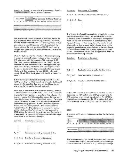
Transfer in Channel. A control lOCO containing a Transferin Channe I command has the fo Ilowi ng format:LocationsOescri pti on of CommandA +6, A + 7 Transfer in Channel to location A +4.A+8,A+9Stop<strong>The</strong> Transfer in Channel command is executed within thelOP and has no direct effect on any of the I/o elementsexternal to the addressed lOP. <strong>The</strong> primary purpose of thiscommand is to permit branching within the command list(i. e., fetching the next operational lOCO from a pair ofmemory word locations other than the next two consecutiveword I ocati ons).When the lOP executes the Transfer in Channel command,it loads the command address register of the appropriateI/o subchannel with the contents of bit positions 13-31(the "next command doubleword address" field), fetchesand loads the new operational 10CD into appropriate registerswithin the I/O subchannel and order register withinthe device controller/device (unless data chaining is specified),and then executes the new lOCO. (Bit positions8-12 and 32-61 are ignored and should be coded aszeros. )If data chaining or command chaining is specified in thelOCO preceding the lOCO containing a Transfer in Channelcommand, the chaining flags are not significant to noraltered by the Transfer in Channel command.When used in conjunction with command chaining, Transferin Channel command faci litates the control of devi ces suchas unbuffered card punches or unbuffered line printers. Forexample, assume that it is desired to present the same cardimage twelve times to an unbuffered card punch. <strong>The</strong> punchcounts the number of times that a record is presented to itand automatically generates a "chain modifier" signal whentwelve rows have been pu·nched. <strong>The</strong> command addressregister within the I/o subchannel is incremented by twoby the "chain modifier" signal and the next consecutivelOCO within the command list is skipped over (not fetchedor executed). A command list for punching two cards mightbe as shown in the following example:<strong>The</strong> Transfer in Channel command can be used also in conjunctionwith data chaining. As one example, considera situation often encountered in data acquisition applications,where data is transmitted in extremely long, contiguousstreams. In this case, the data can be storedalternately in two or more buffer storage areas so that<strong>computer</strong> processing can be carried out on the data in onebuffer whi Ie additional data is being input into the otherbuffer. <strong>The</strong> command list for such an application might beshown in the following example:LocationsOescri pti on of CommandB, B + 1 Read data, store in buffer 1, data chain.B+2, B+3Store into buffer 2, data chain.B+4, B+5 Transfer in Channel to location B.If the lOP encounters two successive Transfer in Channelcommands, an lOP control error (IOPCE) occurs and theI/O operation is terminated immediately. An 10PCE isreported as status information (bit 13 of register Rul) whenthe BP executes an SIO, HIO, no, or TOV instruction.STOPA control lOCO with a Stop command has the followingformat:LocationsDescription of CommandA, A + 1 Punch row for card 1, command chain.A + 2, A + 3 Transfer in Channe I to locati on A.A +4, A +5Punch row for card 2, command chain.<strong>The</strong> Stop command causes certain devices to stop, generatea "channel end II signal, and also request an I/o interruptif bit 0 in the lOCO is coded as a <strong>1.</strong> If the I/O interruptInput/Output Processor (lOP) Fundamentals 147
- Page 1 and 2:
Xerox 560 ComputerReference Manual9
- Page 5 and 6:
4. INPUT/OUTPUT OPERA TIO NS 142 AG
- Page 7 and 8:
1. XEROX 560 COMPUTER SYSTEMINTRODU
- Page 10 and 11:
Many operations are performed in fl
- Page 12 and 13:
Rapid Context Switching. When respo
- Page 14 and 15:
2. SYSTEM ORGANIZATIONThe elements
- Page 16:
FAST MEMORYARITHMETIC AND CONTROL U
- Page 19 and 20:
INFORMATION BOUNDARIESBasic process
- Page 21 and 22:
(Maximumof eight)Core Core Core Cor
- Page 23 and 24:
3. Diagnostic logic. Each memory dr
- Page 25 and 26:
eference address field of the instr
- Page 27 and 28:
Instruction in memory:Instruction i
- Page 29 and 30:
Real-extended addressing is specifi
- Page 31:
Table 1. Basic Processor Operating
- Page 35 and 36:
DesignationFunctionDesignationFunct
- Page 37 and 38:
InterruptStateDisarmedArmed[$Waitin
- Page 39 and 40:
AddressTable 2. Interrupt Locations
- Page 41 and 42:
is assumed to contain an XPSD or a
- Page 43 and 44:
Table 3. Summary of Trap LocationsL
- Page 45 and 46:
TRAP MASKSThe programmer may mask t
- Page 47 and 48:
PUSH-DOWN STACK LIMIT TRAPPush-down
- Page 49 and 50:
Instruction Name Mnemonic FaultDeci
- Page 51 and 52:
subroutine. However, with certain c
- Page 53 and 54:
3. INSTRUCTION REPERTOIREThis chapt
- Page 55 and 56:
CC1 is unchanged by the instruction
- Page 57 and 58:
Condition code settings:2 3 4 Resul
- Page 59 and 60:
Example 2, odd R field value:Before
- Page 61 and 62:
significance (FS), floating zero (F
- Page 63 and 64:
next sequential register after regi
- Page 65 and 66:
R 1 R2 R3 MeaningoThe effective vir
- Page 67 and 68:
Condition code settings:2 3 4 Resul
- Page 69 and 70:
MIMULTIPLY IMMEDIATE(Immediate oper
- Page 71 and 72:
original contents of register R, re
- Page 73 and 74:
Instruction NameCompare HalfwordMne
- Page 75 and 76:
Condition code settings:2 3 4 Resul
- Page 77 and 78:
2 3 4 Result of ShiftCircular Shift
- Page 79 and 80:
4. At the completion of the left sh
- Page 81 and 82:
Instruction NameFloating Subtract L
- Page 83 and 84:
The following table shows the possi
- Page 85 and 86:
Table 8.Condition Code Settings for
- Page 87 and 88:
PACKED DECIMAL NUMBERSAll decimal a
- Page 89 and 90:
DSTDECIMAL STORE(Byte index alignme
- Page 91 and 92:
If no indirect addressing or indexi
- Page 93 and 94:
Instruction NameMnemonicDesignation
- Page 95 and 96:
Both byte strings are C bytes in le
- Page 97 and 98:
of the destination byte that caused
- Page 99 and 100:
again present, unti I a positive or
- Page 101 and 102: The new contents of register 7 are:
- Page 103 and 104: traps to location X'42 1 as a resul
- Page 105 and 106: If there is sufficient space in the
- Page 107 and 108: If CC1, or CC3, or both CC1 and CC3
- Page 109 and 110: appropriate memory stack locations
- Page 111 and 112: II, EI) are generated by II ORing"
- Page 113 and 114: In the real extended addressing mod
- Page 115 and 116: CAll INSTRUCTIONSEach ofthe four CA
- Page 117 and 118: The XPSD instruction' is used for t
- Page 119 and 120: If (I)1O = 0, trap or interrupt ins
- Page 121 and 122: For either memory map format and ei
- Page 123 and 124: initial value plus the initial valu
- Page 125 and 126: Table 9. Status Word 0Field Bits Co
- Page 127 and 128: READ INTERRUPT INHIBITSThe followin
- Page 129 and 130: Table 11.Read Direct Mode 9 Status
- Page 131 and 132: SET ALARM INDICATORThe following co
- Page 133 and 134: INPUT jOUTPUT INSTRUCTIONSThe I/o i
- Page 135 and 136: Table 13.Description of I/o Instruc
- Page 137 and 138: Table 15.Device Status Byte (Regist
- Page 139 and 140: Table 16. Operational Status Byte (
- Page 141 and 142: Table 19.Status Response Bits for A
- Page 143 and 144: If CC4 = 0, the MIOP is in a normal
- Page 145 and 146: 2 3 4 Meaningo 0 I/o address not re
- Page 147 and 148: The functions of bits within the DC
- Page 149 and 150: 4. Each unit-record controller (int
- Page 151: Interrupt at Channel End (Bit Posit
- Page 155 and 156: Otherwise, the first word of the ne
- Page 157 and 158: Depending upon the characteristics
- Page 159 and 160: change the rate on the primary cons
- Page 161 and 162: Location(hex) (dec)20 3221 3322 342
- Page 163 and 164: Table 22.Diagnostic Control (P-Mode
- Page 165 and 166: at its normal rate (e. g., fixed du
- Page 167 and 168: SET LOW CLOCK MARGINSThis command c
- Page 169 and 170: BP STATUS AND NO.Th i s group of i
- Page 171 and 172: Input5MPri ntout5MFunctionStore X 1
- Page 173 and 174: 6. SYSTEM CONFIGURATION CONTROLPool
- Page 175 and 176: Table 25. Functions of Processor Cl
- Page 177: Table 26. Functions of Memory Unit
- Page 180 and 181: STANDARD 8-BIT COMPUTER CODES (EBCD
- Page 182 and 183: STANDARD SYMBOL-CODE CORRESPONDENCE
- Page 184 and 185: STANDARD SYMBOL-CODE CORRESPONDENCE
- Page 186 and 187: TABLE OF POWERS OF SIXTEEN II162564
- Page 188 and 189: HEXADECIMAL-DECIMAL INTEGER CONVERS
- Page 190 and 191: HEXADECIMAL-DECIMAL INTEGER CONVERS
- Page 192 and 193: HEXADECIMAL-DECIMAL INTEGER CONVERS
- Page 194 and 195: HEXADECIMAL-DECIMAL FRACTION CONVER
- Page 196 and 197: HEXADECIMAL-DECIMAL FRACTION CONVER
- Page 198 and 199: APPENDIX B.GLOSSARY OF SYMBOLIC TER
- Page 200 and 201: TermMeaningTermMeaningWKxWrite key
- Page 202 and 203:
Table C-2. Memory Unit Status Regis
- Page 204 and 205:
Y OYf'lV r'f'lrnf'lrtil"\n'''' ....
- Page 206:
701 South Aviation BoulevardEI Segu