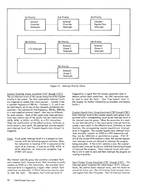
1st Priority 2nd Priority 3rd PriorityInternal External Counter-Override Override Equals-ZeroInterrupts Interrupts Interrupts4th Priority 5th Priority 6th PriorityExternalExternalI/o Interrupts Group 2 Group 4InterruptsInterrupts7th PriorityExternalGroup 5InterruptsFigure 1<strong>1.</strong> Interrupt Priority ChainInternal Override Group (Locations X'52 1 through X'571).<strong>The</strong> six interrupt levels of thi!> group always have the highestpriority in the <strong>system</strong>. <strong>The</strong> four count-pulse interrupt levelsare triggered by pulses from clock sources. Counter 4 hasa constant frequency of 500 Hz. Counters 1, 2, and 3 canbe individua IIy set to any of four manually switchable frequencies- the commercial line frequency, 500 Hz, 2000 Hz,or a user-supplied external signal - that may be differentfor each counter. Each of the count pulse interrupt locationsmust contain one of the modify and test instructions(MTB, MTH, or MTW), an XPSD, or a PSS instruction.H/'-_._ l.'- ____ J!C! __ l.! __ f_C .. L _ _ CC __ L! .• _ L .. L_ L_IC ... __ J __VYIII::I1 1111:: IIIUUIII~UIIUIi \UI 1111:: 1::111::~IIVI:: Uyll::, IIUIIVVUIU, UIword) causes a zero result, the appropriate counter-equalszerointerrupt level (see "Counter-Equals-Zero Group") istriggered.Note: Count pulse interrupt level 4 is a subjective timecounter with the following special attribute: Whenthe instruction in location X '55 1 is executed as theresult of an interrupt, it must be an MTB, MTH, orMTW; otherwise, an instruction exception trap(X '40') will occur.<strong>The</strong> internal override group also contains a processor faultand a memory fault interrupt level. Both locations norma IIycontain an XPSD or a PSS instruction. <strong>The</strong> processor faultinterrupt level is triggered by a signal when certain faultconditions are detected. A POLR instruction must be usedto reset the fault. <strong>The</strong> memory fault interrupt level istriggered by a signal that the memory generates when itdetects certain fault conditions. An LMS instruction mustbe used to reset the fault. (See "Trap System" later inthis chapter for further information on processor and memoryfaults.)Counter-Equals-Zero Group (Locations X 158 1 through X '5B ').Each interrupt I eve lin the counter-equa Is-zero group is associatedwith a corresponding count-pulse interrupt level inthe internal override group. When the execution of a mod-!c.. __ J L __ L ! __.L_•• _L! __ :_ .. L ___•. _ ..__•. 1 __ !_j.___.._j. 1 ___.. : __Ily UIIU IC;)I III;)IIU~IIUII III IIIC ~UUIII-I"UI;)C IIIICIIUI"I IU~UIIUIIcauses a zero result in the effective byte, halfword, or wordlocation, the corresponding counter-equals-zero interruptlevel is triggered. <strong>The</strong> counter-equals-zero interrupt locationsnormally contain an XPSD or a PSS instruction andthey can be i nh ib i ted or permitted as a group. If bit 37(CI) of the current PSW contains a zero, the counter-equalszerointerrupt levels are allowed to interrupt the programbeing executed. If the CI bit contains a one, the counterequals-zerointerrupt levels are inhibited from being allowedto interrupt the program. <strong>The</strong>se interrupt levels wait untilthe C I bit is reset to zero and then interrupt the program accordingto priority.Input/Output Group (Locations X '5C through X '5F'). Thisinterrupt group comprises the input/output (I/O) interruptlevel, the control panel interrupt level, and two levels reservedfor future use. <strong>The</strong> I/O interrupt level accepts interruptsigna Is from the I/o <strong>system</strong>. <strong>The</strong> I/O interrupt location34 Centralized Interrupts
is assumed to contain an XPSD or a PSS instruction thattransfers program control to a routine for servicing all I/ointerrupts. <strong>The</strong> I/o routine should contain an ACK NOWLEDGE I/o INTERRUPT (AIO) instruction that identifies thesource and reason for the interrupt. (<strong>The</strong> AIO instruction isdiscussed in Chapter 3 "Input/Output Instrudions".)<strong>The</strong> control panel interrupt level is activated from the operator1sconsole. This location normally contains an X PSDor a PSS instruction. <strong>The</strong> operator can thus trigger this interruptlevel to initiate a specific routine.<strong>The</strong> interrupt levels in the I/o group can be inhibited orpermitted by means of bit position 38 (II) of the PSWs.If II is reset to zero, interrupt signals affecting the I/ogroup interrupt levels are allowed to interrupt the programbeing executed. If the II bit is set to one, interruptsignals in this group are inhibited from interrupting theprogram.EXTERNAL INTERRUPTSA <strong>system</strong> can contain 4 optional groups of external interruptlevels. <strong>The</strong> external override group, group 3, containsthe first 12 external interrupt levels. External groups 2,4, and 5 each contain 12 external interrupt levels. (SeeTable 2 and Figure 1<strong>1.</strong>) External levels may be triggeredby external sources or via WD instructions, while internallevels may be triggered by internal sources or via WDinstructions.All external interrupt levels normally contain XPSD or PSSinstructions and can be inhibited or permitted by means ofthe setting of bit position 39 (EI) of the program status words.If EI contains a zero, external interrupts are allowed to interrupta program; if EI contains a one, all external interruptsare inhibited from interrupting the program.NUMBER OF INTERRUPT GROUPS<strong>The</strong> 14 internal interrupt levels are standard in every <strong>system</strong>and all external levels are optional. <strong>The</strong> addition of theexternal groups (12 levels per group) raises the number ofinterrupt levels to a maximum of 62.CONTROL OF THE INTERRUPT SYSTEM<strong>The</strong> <strong>system</strong> has two points of interrupt control. One pointof interrupt control is achieved by means of the interruptinhibit bits (CI, II, and EI) in the program status words (PSWs).<strong>The</strong> basic processor is inhibited from interrupting a programif the interrupt inhibit bit for a corresponding class of interruptlevels is set to one, that is, no interrupt level in theinhibited group can advance from the waiting state to theactive state, and the entire group is disabled (removed fromthe interrupt recognition priority chain) • Consequently, awaiting, enabled, interrupt level in an inhibited group doesnot prevent a lower priority, waiting, enabled interruptlevel in an uninhibited group from interrupting the program.However, if an interrupt group is inhibited while a level inthat group is in the active state, no lower priority interruptlevel can advance to the active state.Note also this special case: When the processor detectedfault (PDF) flag is set to 1 (see "Processor Detected Faults Jl ,later in this chapter), the processor fault, memory fault, andcount pulse interrupts are automatica lIy inhibited.<strong>The</strong> second point of interrupt control is at the individual interruptlevel. <strong>The</strong> basic processor can interact with anyinterrupt level by means of special modes of the RD and WDinstructions (described in Chapter 3, JlControl Instructions Jl ).For this purpose, the interrupt levels are organized into thefollowing DIO address groups (see last two columns inTable 2):<strong>1.</strong> <strong>The</strong> 14 levels of internal interrupts (internal overridegroup, counter-equals-zero group, and I/o group) aredesignated as group code 0 in bits 28-31 of the effectiveaddress of the RD or WD instruction.2. <strong>The</strong> 12 levels of each group of external interrupts aredesignated as group codes 2, 3, 4, and 5. That is,external group 2 is designated group code 2, externalgroup 3 is designated group code 3, etc.3. <strong>The</strong>re is no group code <strong>1.</strong><strong>The</strong> addressing of an individual interrupt level within itsDIO group of 12 or 14 is accomplished by an assigned selectionbit within the low-order 16-bit positions of the R registerdesignated in the RD or WD instruction (see lastcolumn in Table 2).<strong>The</strong> WD instruction can individually arm, disarm, enable,disable, or trigger (move to the active state) any interruptlevel. <strong>The</strong> RD instruction can determine which interruptlevels within a selected DIO group are in the armed orwaiting state, waiting or active state, or are enabled.TIME OF INTERRUPT OCCURRENCES<strong>The</strong> basic processor permits an interrupt to occur during thefollowing time intervals (related to the execution cycle ofan instruction) provided the SCP basic processor (BP) statusindicators are either in the RUN or WAIT condition:<strong>1.</strong> Between instructions an interrupt is permitted betweenthe completion of any instruction and the initiation ofthe next instruction.2. Between instruction initiations an interrupt is also permittedto occur during the execution of the followingmultiple-operand instructions:MOVE BYTE STRING (MBS)COMPARE BYTE STRING (CBS)TRANSLATE BYTE STRING (TBS)Centralized Interrupts 35
- Page 1 and 2: Xerox 560 ComputerReference Manual9
- Page 5 and 6: 4. INPUT/OUTPUT OPERA TIO NS 142 AG
- Page 7 and 8: 1. XEROX 560 COMPUTER SYSTEMINTRODU
- Page 10 and 11: Many operations are performed in fl
- Page 12 and 13: Rapid Context Switching. When respo
- Page 14 and 15: 2. SYSTEM ORGANIZATIONThe elements
- Page 16: FAST MEMORYARITHMETIC AND CONTROL U
- Page 19 and 20: INFORMATION BOUNDARIESBasic process
- Page 21 and 22: (Maximumof eight)Core Core Core Cor
- Page 23 and 24: 3. Diagnostic logic. Each memory dr
- Page 25 and 26: eference address field of the instr
- Page 27 and 28: Instruction in memory:Instruction i
- Page 29 and 30: Real-extended addressing is specifi
- Page 31: Table 1. Basic Processor Operating
- Page 35 and 36: DesignationFunctionDesignationFunct
- Page 37 and 38: InterruptStateDisarmedArmed[$Waitin
- Page 39: AddressTable 2. Interrupt Locations
- Page 43 and 44: Table 3. Summary of Trap LocationsL
- Page 45 and 46: TRAP MASKSThe programmer may mask t
- Page 47 and 48: PUSH-DOWN STACK LIMIT TRAPPush-down
- Page 49 and 50: Instruction Name Mnemonic FaultDeci
- Page 51 and 52: subroutine. However, with certain c
- Page 53 and 54: 3. INSTRUCTION REPERTOIREThis chapt
- Page 55 and 56: CC1 is unchanged by the instruction
- Page 57 and 58: Condition code settings:2 3 4 Resul
- Page 59 and 60: Example 2, odd R field value:Before
- Page 61 and 62: significance (FS), floating zero (F
- Page 63 and 64: next sequential register after regi
- Page 65 and 66: R 1 R2 R3 MeaningoThe effective vir
- Page 67 and 68: Condition code settings:2 3 4 Resul
- Page 69 and 70: MIMULTIPLY IMMEDIATE(Immediate oper
- Page 71 and 72: original contents of register R, re
- Page 73 and 74: Instruction NameCompare HalfwordMne
- Page 75 and 76: Condition code settings:2 3 4 Resul
- Page 77 and 78: 2 3 4 Result of ShiftCircular Shift
- Page 79 and 80: 4. At the completion of the left sh
- Page 81 and 82: Instruction NameFloating Subtract L
- Page 83 and 84: The following table shows the possi
- Page 85 and 86: Table 8.Condition Code Settings for
- Page 87 and 88: PACKED DECIMAL NUMBERSAll decimal a
- Page 89 and 90: DSTDECIMAL STORE(Byte index alignme
- Page 91 and 92:
If no indirect addressing or indexi
- Page 93 and 94:
Instruction NameMnemonicDesignation
- Page 95 and 96:
Both byte strings are C bytes in le
- Page 97 and 98:
of the destination byte that caused
- Page 99 and 100:
again present, unti I a positive or
- Page 101 and 102:
The new contents of register 7 are:
- Page 103 and 104:
traps to location X'42 1 as a resul
- Page 105 and 106:
If there is sufficient space in the
- Page 107 and 108:
If CC1, or CC3, or both CC1 and CC3
- Page 109 and 110:
appropriate memory stack locations
- Page 111 and 112:
II, EI) are generated by II ORing"
- Page 113 and 114:
In the real extended addressing mod
- Page 115 and 116:
CAll INSTRUCTIONSEach ofthe four CA
- Page 117 and 118:
The XPSD instruction' is used for t
- Page 119 and 120:
If (I)1O = 0, trap or interrupt ins
- Page 121 and 122:
For either memory map format and ei
- Page 123 and 124:
initial value plus the initial valu
- Page 125 and 126:
Table 9. Status Word 0Field Bits Co
- Page 127 and 128:
READ INTERRUPT INHIBITSThe followin
- Page 129 and 130:
Table 11.Read Direct Mode 9 Status
- Page 131 and 132:
SET ALARM INDICATORThe following co
- Page 133 and 134:
INPUT jOUTPUT INSTRUCTIONSThe I/o i
- Page 135 and 136:
Table 13.Description of I/o Instruc
- Page 137 and 138:
Table 15.Device Status Byte (Regist
- Page 139 and 140:
Table 16. Operational Status Byte (
- Page 141 and 142:
Table 19.Status Response Bits for A
- Page 143 and 144:
If CC4 = 0, the MIOP is in a normal
- Page 145 and 146:
2 3 4 Meaningo 0 I/o address not re
- Page 147 and 148:
The functions of bits within the DC
- Page 149 and 150:
4. Each unit-record controller (int
- Page 151 and 152:
Interrupt at Channel End (Bit Posit
- Page 153 and 154:
Transfer in Channel. A control lOCO
- Page 155 and 156:
Otherwise, the first word of the ne
- Page 157 and 158:
Depending upon the characteristics
- Page 159 and 160:
change the rate on the primary cons
- Page 161 and 162:
Location(hex) (dec)20 3221 3322 342
- Page 163 and 164:
Table 22.Diagnostic Control (P-Mode
- Page 165 and 166:
at its normal rate (e. g., fixed du
- Page 167 and 168:
SET LOW CLOCK MARGINSThis command c
- Page 169 and 170:
BP STATUS AND NO.Th i s group of i
- Page 171 and 172:
Input5MPri ntout5MFunctionStore X 1
- Page 173 and 174:
6. SYSTEM CONFIGURATION CONTROLPool
- Page 175 and 176:
Table 25. Functions of Processor Cl
- Page 177:
Table 26. Functions of Memory Unit
- Page 180 and 181:
STANDARD 8-BIT COMPUTER CODES (EBCD
- Page 182 and 183:
STANDARD SYMBOL-CODE CORRESPONDENCE
- Page 184 and 185:
STANDARD SYMBOL-CODE CORRESPONDENCE
- Page 186 and 187:
TABLE OF POWERS OF SIXTEEN II162564
- Page 188 and 189:
HEXADECIMAL-DECIMAL INTEGER CONVERS
- Page 190 and 191:
HEXADECIMAL-DECIMAL INTEGER CONVERS
- Page 192 and 193:
HEXADECIMAL-DECIMAL INTEGER CONVERS
- Page 194 and 195:
HEXADECIMAL-DECIMAL FRACTION CONVER
- Page 196 and 197:
HEXADECIMAL-DECIMAL FRACTION CONVER
- Page 198 and 199:
APPENDIX B.GLOSSARY OF SYMBOLIC TER
- Page 200 and 201:
TermMeaningTermMeaningWKxWrite key
- Page 202 and 203:
Table C-2. Memory Unit Status Regis
- Page 204 and 205:
Y OYf'lV r'f'lrnf'lrtil"\n'''' ....
- Page 206:
701 South Aviation BoulevardEI Segu