Duality SE Operator's Manual - Solid State Logic
Duality SE Operator's Manual - Solid State Logic
Duality SE Operator's Manual - Solid State Logic

Create successful ePaper yourself
Turn your PDF publications into a flip-book with our unique Google optimized e-Paper software.
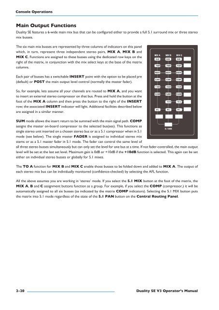
Console OperationsMain Output Functions<strong>Duality</strong> <strong>SE</strong> features a 6-wide main mix bus that can be configured either to provide a full 5.1 surround mix or three stereomix busses.The six main mix busses are represented by three columns of indicators on this panelwhich, in turn, represent three independent stereo pairs, MIx a, MIx B andMIx C. Functions are assigned to these busses using the dedicated row keys on theright of the matrix, in conjunction with the mix select keys at the base of the matrixcolumns.Each pair of busses has a switchable Insert point with the option to be placed pre(default) or pOst the main output level control (normally the master fader).So, for example, lets assume all your channels are routed to MIx a, and you wantto insert an external stereo compressor on that bus. Press and hold the button at thefoot of the MIx a column and then press the button to the right of the Insertrow; the associated Insert indicator will light. Additional facilities described beloware assigned in a similar manner.suM mode allows the insert return to be summed with the main signal path. COMpassigns the master on-board compressor to the selected bus(ses). This functions assingle stereo unit inserted on a chosen stereo bus or as a 5.1 compressor when in 5.1mode (see below). The single master FaDer is assigned to individual stereo mixstems or as a 5.1 master fader in 5.1 mode. The fader can control the same level ofall three stereo busses simultaneously but can only set the level for one bus at a time. If not fader-controlled, the main outputlevel will be set at the last set level. Maximum gain is 0dB or +10dB if the +10dB function is selected. This again can be seteither on individual stereo busses or globally for 5.1 mixes.The tO a function for MIx B and MIx C enable those busses to be folded down and added to MIx a. The output ofeach stereo mix bus can be individually monitored (confidence-checked) by selecting the AFL function.All the above assumes you are working in ‘stereo’ mode. If you select the 5.1 MIx button at the foot of the matrix, theMIx a, B and C assignment buttons function as a group. For example, if you select the COMp (compressor,) it will beautomatically assigned to all six busses (as indicated by the matrix COMp indicators). Selecting the 5.1 MIX button putsthe matrix into 5.1 mode regardless of the state of the 5.1 pan button on the Central routing panel.2-20 <strong>Duality</strong> se V3 Operator’s <strong>Manual</strong>