Viessmann Katalog 2019/2020/2021
Viessmann Gesamtkatalog DE/EN 2019/2020/2021
Viessmann Gesamtkatalog DE/EN 2019/2020/2021

Erfolgreiche ePaper selbst erstellen
Machen Sie aus Ihren PDF Publikationen ein blätterbares Flipbook mit unserer einzigartigen Google optimierten e-Paper Software.
Commander<br />
1 2 3 4 5 6 7 8<br />
H0<br />
Multiplex-Technologie...<br />
Die Multiplex-Technologie ermöglicht die gleichzeitige Übertragung<br />
der Befehle mehrerer Signale über eine Leitung. Diese in<br />
der Telekommunikation etablierte Technik nutzt für jedes Signal<br />
eine eigene Frequenz.<br />
Nur wenige Kabel!<br />
Multiplex-Technologie bei der Modellbahn:<br />
Bei der Modellbahn möchte man möglichst wenige Kabel verlegen.<br />
Dies ist bei der digitalen Steuerung von Modelleisenbahnen<br />
Standard.<br />
Die Verbindung zwischen Decoder und Signal erfolgte bisher<br />
aber sehr aufwendig, z. B. bei einem Hauptsignal mit Vorsignal<br />
mit 10 Kabeln. Hinzu kommen Relais, Schalter und Verbindungskabel.<br />
Bei mehreren Signalen wird es unübersichtlich<br />
und dicke Kabelstränge stören das vorbildgerechte Aussehen<br />
der Signale.<br />
Bei der Multiplex-Technologie ist nur ein 4-poliges Kabel mit<br />
Steckern zwischen Signal und Ansteuerung nötig: Einfach, aufgeräumt,<br />
übersichtlich.<br />
Einfaches Schalten komplexer Signalbilder<br />
Zum Ansteuern eines Signals mit Vorsignal würden bei analoger<br />
Technik insgesamt 9 Einschalter oder Relais benötigt.<br />
Ist das Hauptsig-nal auf Hp0 „Halt“ geschaltet, so muss das<br />
Vorsignal direkt darunter komplett ausgeschaltet sein: Ein weiterer<br />
Schalter würde erforderlich.Umfangreiche Kombinationen<br />
aus Umschaltern, logischen Verknüpfungen usw. sind notwendig,<br />
um korrekte Signalbilder zu gewährleisten. In den Multiplexer-Steuermodulen<br />
sind sie in der Elektronik integriert: für<br />
analoge und digitale Ansteuerung.<br />
Korrekte Darstellung hintereinander geschalteter Signale<br />
Multiplexer hintereinander geschalteter Signale werden über 2<br />
Kabel miteinander verbunden: Zeigt das nachfolgende Signal<br />
Multiplex-technology...<br />
It facilitates the simultaneous transmission of the commands for<br />
several signals via one line. The technology is established in<br />
the telecommunications industry and utilizes its own frequency<br />
for each signal.<br />
Hardly any cables needed!<br />
Multiplex-technology for model trains<br />
Model train enthusiasts want to do as little wiring as possible.<br />
This is standard for digital model train systems.<br />
However, the wiring from the decoder to the signal has been<br />
quite complex in the past. Thus one needed, for instance, 10<br />
cables for a main signal with distant signal on the same mast. In<br />
addition, relays, switches and connecting cables were required.<br />
It is quite complex to wire several signals with thick cable harnesses<br />
leading to the signal head, which destroy the illusion of<br />
the characteristic appearance of prototypical signals.<br />
With multiplex-technology only a 4-pole cable is needed. This<br />
cable coming from the signal is simply plugged into the decoder:<br />
Easy, tidy, clearly arranged.<br />
Simple switching of complex signal aspects<br />
In analogue technology the wiring of a signal with distant signal<br />
on the same mast would require 9 switches or relays in total.<br />
Assuming the main signal shows Hp0 (“Stop”), then the distant<br />
signal below must be completely dark. Yet another switch would<br />
be required. Extensive combinations of change-over switches,<br />
logic links etc. are necessary in order to assure that correct signal<br />
aspects are displayed. All necessary switching components<br />
are integral parts of the multiplex decoder – both for analogue<br />
and digital control.<br />
Correct display of signals further down the line<br />
Multiplex decoders controlling signals along the main line in<br />
sequence may be connected to each other with two cables: If<br />
the following signal displays Hp0 (“Stop”), then the distant signal<br />
on the mast of the “local” main signal must show Vr0 (“Expect<br />
to Stop”).<br />
The same goes for the aspects Hp1/Vr1 “Proceed”/“Expect<br />
to proceed at next signal” and Hp2/Vr2 “Proceed at reduced<br />
Hp0 „Halt“ an, so wird beim hiesigen Vorsignal Vr0 „Halt erwarten“<br />
angezeigt.<br />
Entsprechendes gilt für Hp1/Vr1 „Fahrt“/“Fahrt erwarten“ und<br />
Hp2/Vr2 „Langsamfahrt“/“Langsamfahrt erwarten“. Zeigt das<br />
Hauptsignal, das über dem Vorsignal montiert ist, Hp0 „Halt“<br />
an, so wird das Vorsignal vorbildgerecht abgedunkelt.<br />
Einstellbar<br />
Über DIP-Schalter der Multiplexer lassen sich unterschiedliche<br />
Funktionen einstellen: weiches, vorbildgerechtes Umschalten<br />
der Signalbilder oder direktes Umschalten, Einsatz als Blockoder<br />
Bahnhofssignal usw.<br />
LED-Lichtsignale<br />
Langlebig, stromsparend, minimaler Stromverbrauch, keine<br />
Wärmeentwicklung.<br />
Vorteile<br />
Analog – wenig Trafoleistung erforderlich.<br />
Digital – keine zusätzliche Stromversorgung erforderlich.<br />
Welche Steuerbausteine?<br />
Multiplexer Art. 5229 :Für ein Haupt- und ein Vorsignal, die an<br />
einem Mast montiert sind und ein Hauptsignal mit separat stehendem<br />
Vorsignal.<br />
Doppel-Multiplexer Art. 52292: Für 2 Hauptsignale ohne Vorsignale,<br />
z. B. bei Blocksig nalen Art. 4721.<br />
Hightech in H0: Besonders komfortabel ist die Multiplex-Technologie<br />
in Kombination mit dem <strong>Viessmann</strong> Commander. Die<br />
Sig naltypen werden automatisch erkannt und als Gleisplansymbol<br />
auf dem Display angezeigt.<br />
speed”/“Expect to proceed at reduced speed at the next signal”.<br />
If the main signal mounted above the distant signal displays<br />
Hp0 “Stop”, then the distant signal will – like the prototype – be<br />
turned off completely.<br />
Adjustable<br />
Several functions for the outputs can be set by means of DIP<br />
switches installed on the multiplexer: Soft, prototypical changeover<br />
of signal aspects or direct change-over, utilization as block<br />
signal or as yard signal, etc.<br />
LED colour light signals<br />
Long-lived, energy saving with minimal power consumption, no<br />
heat generation.<br />
Advantages<br />
Analogue mode: Low power from the transformer required.<br />
Digital mode: No additional power supply required.<br />
Which control modules?<br />
Multiplex decoder item 5229: For a main and distant signal<br />
mounted on the same mast.<br />
Multiplex decoder item 52292: For 2 main signals without distant<br />
signals, e. g.: Block signals item 4721.<br />
Hightech in H0 The ultimate comfort is achieved when combining<br />
the multiplex-technology with the <strong>Viessmann</strong> Commander.<br />
The signal types are automatically detected and recognised<br />
and are immediately displayed with the correct symbol on the<br />
touch screen.<br />
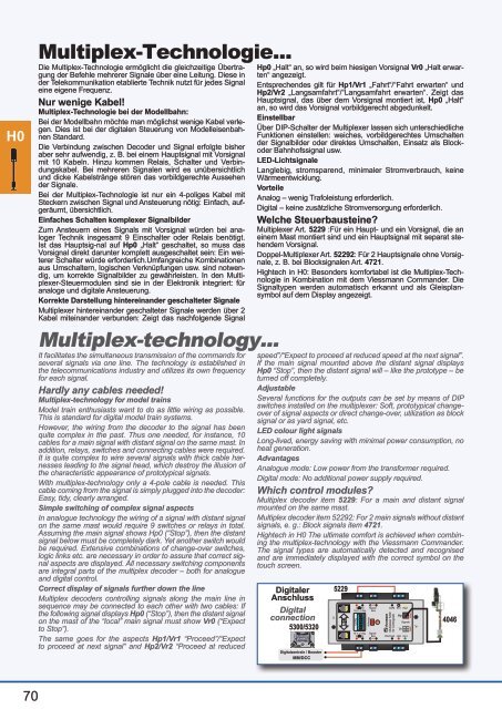
Digitaler<br />
Anschluss<br />
Digital<br />
connection<br />
5300/5320<br />
Digitalzentrale / Booster<br />
MM/DCC<br />
5229<br />
LSB<br />
rt bn<br />
16 V ~/ Dig.<br />
ON<br />
WnP<br />
16 V ~/ Dig.<br />
rt bn<br />
Signal-<br />
Bus<br />
Signal-<br />
Bus<br />
COM Sh1<br />
viessmann<br />
Multiplexer 5229<br />
für Lichtsignale<br />
Hp2<br />
Art. Hp04046<br />
Hp1<br />
Bremsen<br />
Hp<br />
Vr<br />
Signale<br />
4046<br />
70