Humminbird - Fish Finders and GPS
Humminbird - Fish Finders and GPS
Humminbird - Fish Finders and GPS

You also want an ePaper? Increase the reach of your titles
YUMPU automatically turns print PDFs into web optimized ePapers that Google loves.
1<br />
2<br />
3<br />
4<br />
5<br />
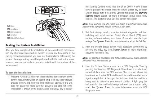
Power<br />
Temp/Speed<br />
Communications<br />
Transducer<br />
Cable Collector Insert<br />
Testing the System Installation<br />
5<br />
1 2 3 4<br />
After you have completed the installation of the control head, transducer,<br />
<strong>and</strong> any other accessories such as the <strong>GPS</strong> receiver, <strong>and</strong> have made all the<br />
cabling connections required, you must test the installation before using the<br />
system. Thorough testing should be performed with the boat in the water;<br />
however, you can confirm basic operation initially with the boat out of the<br />
water as well.<br />
To test the installation:<br />
1. Press the POWER/LIGHT key on the control head once to turn on the<br />
control head. (There will be an audible chirp to let you know that you<br />
pressed the key, <strong>and</strong> the initial Title screen will appear.) If the unit<br />
does not power up, make sure that power is available. While the<br />
Title screen is shown on the display, press the MENU key to display<br />
the Start-Up Options menu. Use the UP or DOWN 4-WAY Cursor<br />
keys to position the cursor, then the RIGHT Cursor key to select<br />
System Status from the Start-Up Options menu (see the Start-Up<br />
Options Menu section for more information about these menu<br />
choices). The System Status Self Test screen will appear.<br />
NOTE: If you wait too long, the system will default to whichever menu mode<br />
happens to be highlighted, <strong>and</strong> you will have to start again.<br />
2. Self Test displays results from the internal diagnostic self test,<br />
including unit serial number, Printed Circuit Board (PCB) serial<br />
number, software revision, total hours of operation <strong>and</strong> the input<br />
voltage. See System Status for more information about the Self Test.<br />
3. From the System Status screen, view accessory connections by<br />
pressing the VIEW key. See System Status for more information<br />
about the Accessory Test.<br />
NOTE: The speed will be detected only if the paddlewheel has moved since the<br />
900 Series has been powered up.<br />
4. From the System Status screen, see a <strong>GPS</strong> Diagnostic View by<br />
pressing the View key. <strong>GPS</strong> Diagnostic View shows a sky chart <strong>and</strong><br />
numerical data from the <strong>GPS</strong> receiver. The sky chart shows the<br />
location of each visible <strong>GPS</strong> satellite with its satellite number <strong>and</strong> a<br />
signal strength bar. A dark grey bar indicates that the satellite is<br />
being used to determine your current position. A light gray bar<br />
indicates that the satellite is being monitored, but is not yet being<br />
used. See System Status for more information about the <strong>GPS</strong><br />
Diagnostic View.<br />
24