STX Signal Transmitter Installation and Operation ... - Kistler-Morse
STX Signal Transmitter Installation and Operation ... - Kistler-Morse
STX Signal Transmitter Installation and Operation ... - Kistler-Morse
You also want an ePaper? Increase the reach of your titles
YUMPU automatically turns print PDFs into web optimized ePapers that Google loves.
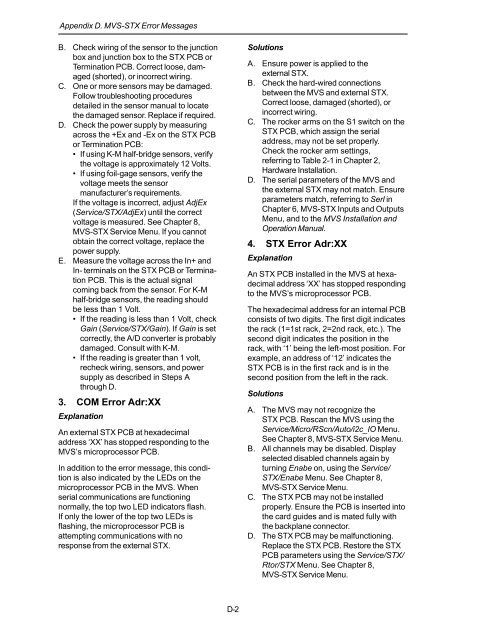
Appendix D. MVS-<strong>STX</strong> Error Messages<br />
B. Check wiring of the sensor to the junction<br />
box <strong>and</strong> junction box to the <strong>STX</strong> PCB or<br />
Termination PCB. Correct loose, damaged<br />
(shorted), or incorrect wiring.<br />
C. One or more sensors may be damaged.<br />
Follow troubleshooting procedures<br />
detailed in the sensor manual to locate<br />
the damaged sensor. Replace if required.<br />
D. Check the power supply by measuring<br />
across the +Ex <strong>and</strong> -Ex on the <strong>STX</strong> PCB<br />
or Termination PCB:<br />
• If using K-M half-bridge sensors, verify<br />
the voltage is approximately 12 Volts.<br />
• If using foil-gage sensors, verify the<br />
voltage meets the sensor<br />
manufacturer’s requirements.<br />
If the voltage is incorrect, adjust AdjEx<br />
(Service/<strong>STX</strong>/AdjEx) until the correct<br />
voltage is measured. See Chapter 8,<br />
MVS-<strong>STX</strong> Service Menu. If you cannot<br />
obtain the correct voltage, replace the<br />
power supply.<br />
E. Measure the voltage across the In+ <strong>and</strong><br />
In- terminals on the <strong>STX</strong> PCB or Termination<br />
PCB. This is the actual signal<br />
coming back from the sensor. For K-M<br />
half-bridge sensors, the reading should<br />
be less than 1 Volt.<br />
• If the reading is less than 1 Volt, check<br />
Gain (Service/<strong>STX</strong>/Gain). If Gain is set<br />
correctly, the A/D converter is probably<br />
damaged. Consult with K-M.<br />
• If the reading is greater than 1 volt,<br />
recheck wiring, sensors, <strong>and</strong> power<br />
supply as described in Steps A<br />
through D.<br />
3. COM Error Adr:XX<br />
Explanation<br />
An external <strong>STX</strong> PCB at hexadecimal<br />
address ‘XX’ has stopped responding to the<br />
MVS’s microprocessor PCB.<br />
In addition to the error message, this condition<br />
is also indicated by the LEDs on the<br />
microprocessor PCB in the MVS. When<br />
serial communications are functioning<br />
normally, the top two LED indicators flash.<br />
If only the lower of the top two LEDs is<br />
flashing, the microprocessor PCB is<br />
attempting communications with no<br />
response from the external <strong>STX</strong>.<br />
Solutions<br />
A. Ensure power is applied to the<br />
external <strong>STX</strong>.<br />
B. Check the hard-wired connections<br />
between the MVS <strong>and</strong> external <strong>STX</strong>.<br />
Correct loose, damaged (shorted), or<br />
incorrect wiring.<br />
C. The rocker arms on the S1 switch on the<br />
<strong>STX</strong> PCB, which assign the serial<br />
address, may not be set properly.<br />
Check the rocker arm settings,<br />
referring to Table 2-1 in Chapter 2,<br />
Hardware <strong>Installation</strong>.<br />
D. The serial parameters of the MVS <strong>and</strong><br />
the external <strong>STX</strong> may not match. Ensure<br />
parameters match, referring to Serl in<br />
Chapter 6, MVS-<strong>STX</strong> Inputs <strong>and</strong> Outputs<br />
Menu, <strong>and</strong> to the MVS <strong>Installation</strong> <strong>and</strong><br />
<strong>Operation</strong> Manual.<br />
4. <strong>STX</strong> Error Adr:XX<br />
Explanation<br />
An <strong>STX</strong> PCB installed in the MVS at hexadecimal<br />
address ‘XX’ has stopped responding<br />
to the MVS’s microprocessor PCB.<br />
The hexadecimal address for an internal PCB<br />
consists of two digits. The first digit indicates<br />
the rack (1=1st rack, 2=2nd rack, etc.). The<br />
second digit indicates the position in the<br />
rack, with ‘1’ being the left-most position. For<br />
example, an address of ‘12’ indicates the<br />
<strong>STX</strong> PCB is in the first rack <strong>and</strong> is in the<br />
second position from the left in the rack.<br />
Solutions<br />
A. The MVS may not recognize the<br />
<strong>STX</strong> PCB. Rescan the MVS using the<br />
Service/Micro/RScn/Auto/i2c_IO Menu.<br />
See Chapter 8, MVS-<strong>STX</strong> Service Menu.<br />
B. All channels may be disabled. Display<br />
selected disabled channels again by<br />
turning Enabe on, using the Service/<br />
<strong>STX</strong>/Enabe Menu. See Chapter 8,<br />
MVS-<strong>STX</strong> Service Menu.<br />
C. The <strong>STX</strong> PCB may not be installed<br />
properly. Ensure the PCB is inserted into<br />
the card guides <strong>and</strong> is mated fully with<br />
the backplane connector.<br />
D. The <strong>STX</strong> PCB may be malfunctioning.<br />
Replace the <strong>STX</strong> PCB. Restore the <strong>STX</strong><br />
PCB parameters using the Service/<strong>STX</strong>/<br />
Rtor/<strong>STX</strong> Menu. See Chapter 8,<br />
MVS-<strong>STX</strong> Service Menu.<br />
D-2


