

STX Signal Transmitter Installation and Operation ... - Kistler-Morse
STX Signal Transmitter Installation and Operation ... - Kistler-Morse
STX Signal Transmitter Installation and Operation ... - Kistler-Morse

Create successful ePaper yourself
Turn your PDF publications into a flip-book with our unique Google optimized e-Paper software.
Appendix E. Trimming the Current Output<br />
Appendix E. Trimming the<br />
Current Output<br />
If the calibration of the device receiving the<br />
current output does not match the calibration<br />
of the Current Output PCB (soldered to the<br />
<strong>STX</strong> PCB), follow this procedure to ‘trim’ the<br />
<strong>STX</strong>’s current output:<br />
1. See Figure E-1 <strong>and</strong> TI-SP.<strong>STX</strong>-02 (st<strong>and</strong>alone),<br />
TI-SP.<strong>STX</strong>-03 (st<strong>and</strong>ard 19” rack),<br />
or TI-MVS.<strong>STX</strong>-01 (MVS-<strong>STX</strong>) in<br />
Appendix H.<br />
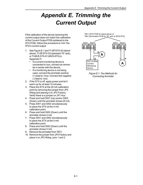
• If a current monitoring device is<br />
connected to Iout, connect an ammeter<br />
in series with the device.<br />
• If a monitoring device is not being<br />
used, connect the ammeter positive<br />
(+) lead to +Iout. Connect the negative<br />
(-) lead to -Iout.<br />
2. If the <strong>STX</strong> is off, apply power <strong>and</strong> let it<br />
warm up for at least 15 minutes.<br />
3. Place the <strong>STX</strong> at the 20 mA calibration<br />
point by removing the jumper from JP3<br />
Wdog <strong>and</strong> placing it on JP2 Factory.<br />
Verify there is a jumper on JP1 Aux.<br />
4. Press <strong>and</strong> hold SW1 (Up) <strong>and</strong>/or SW2<br />
(Down) until the ammeter shows 20 mA.<br />
5. Press SW1 <strong>and</strong> SW2 simultaneously<br />
to place the <strong>STX</strong> at the 4 mA<br />
calibration point.<br />
6. Press <strong>and</strong> hold SW2 (Down) until the<br />
ammeter shows 4 mA.<br />
7. Press SW1 <strong>and</strong> SW2 simultaneously<br />
to place the <strong>STX</strong> at the 0 mA<br />
calibration point.<br />
8. Press <strong>and</strong> hold SW2 (Down) until the<br />
ammeter shows 0 mA.<br />
9. Remove the ammeter from TB11.<br />
10. Remove the jumper from JP2 Factory <strong>and</strong><br />
place it on JP3 Wdog, pins 1 <strong>and</strong> 2.<br />
TB11 (<strong>STX</strong> PCB for st<strong>and</strong>-alone) or<br />
TB4 (Termination PCB for 19” rack or MVS-<strong>STX</strong>)<br />
-EXT+<br />
-IOUT+<br />
- +<br />
- +<br />
PLC or other<br />
Current<br />
Monitoring<br />
Device<br />
- +<br />
A<br />
-EXT+<br />
Figure E-1. Two Methods for<br />
Connecting Ammeter<br />
-IOUT+<br />
- +<br />
- +<br />
A<br />
E-1


