

STX Signal Transmitter Installation and Operation ... - Kistler-Morse
STX Signal Transmitter Installation and Operation ... - Kistler-Morse
STX Signal Transmitter Installation and Operation ... - Kistler-Morse

You also want an ePaper? Increase the reach of your titles
YUMPU automatically turns print PDFs into web optimized ePapers that Google loves.
Chapter 8. MVS-<strong>STX</strong> Service Menu<br />
• Material tracking establishes a reference<br />
when material movement within a<br />
vessel has become stable (rate of change<br />
is below the threshold) during filling <strong>and</strong><br />
batching processes. This reference is<br />
then used to maintain <strong>and</strong> hold steady the<br />
outputs. When the change in raw voltage<br />
falls within the drift limit (factory set at<br />
± 5.00 mV), the corrected voltage <strong>and</strong><br />
counts remain those associated with the<br />
reference weight. The correction is done<br />
by the algebraic addition of a correction<br />
offset to the A/D converter output. The<br />
maximum accumulated correction offset<br />
is limited to ± 5.0 mV. If the accumulated<br />
drift exceeds 5.0 mV, the <strong>STX</strong> begins<br />
tracking the material movement, which<br />
may be caused by a slow leak in the<br />
vessel. Material tracking affects setpoints,<br />
current output, <strong>and</strong> serial output as well<br />
as the channel monitoring display.<br />
The selections for Trk apply only to the<br />
current channel.<br />
Tracking can be used in any of the<br />
following combinations:<br />
• No zero or material tracking<br />
• Zero tracking only<br />
• Material tracking only<br />
• Zero tracking <strong>and</strong> material tracking<br />
Trk has four submenus:<br />
Win (window size)<br />
This function sets the maximum plus or minus<br />
offset value for zero tracking. If the minus<br />
offset value is exceeded, the MVS resets the<br />
zero calibration point. The default is .00 mV —<br />
at this value, zero tracking is turned off.<br />
Matrl (material tracking enable)<br />
This function turns material tracking on <strong>and</strong><br />
off. The default is Off.<br />
Rate<br />
This function sets the threshold rate in<br />
uV/sec for both zero <strong>and</strong> material tracking.<br />
When the rate of change exceeds this value,<br />
indicating that material is actually moving, the<br />
<strong>STX</strong> stops tracking until the rate of change<br />
again falls below this value. The default is<br />
± 5.0 uV/sec.<br />
Dflt (default)<br />
This function resets the zero <strong>and</strong> material<br />
tracking parameters to factory-set defaults.<br />
SetPt (setpoint relays)<br />
This menu turns the setpoint relays on <strong>and</strong> off<br />
for test purposes. The MVS displays a<br />
warning that automatic control of the<br />
setpoints assigned to the currently selected<br />
channel is transferred to manual control, <strong>and</strong><br />
requests verification.<br />
CAUTION<br />
Manually activating setpoint relays<br />
may cause damage if control equipment<br />
is connected. Disconnect control<br />
equipment before proceeding.<br />
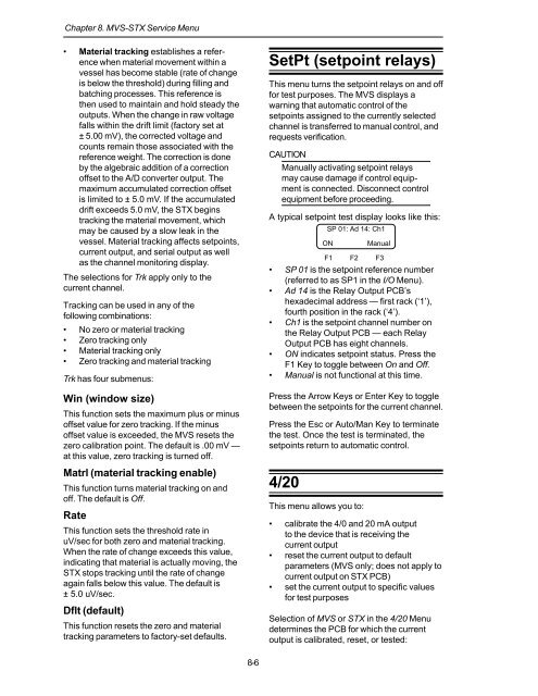
A typical setpoint test display looks like this:<br />
SP 01: Ad 14: Ch1<br />
F1 F2 F3<br />
• SP 01 is the setpoint reference number<br />
(referred to as SP1 in the I/O Menu).<br />
• Ad 14 is the Relay Output PCB’s<br />
hexadecimal address — first rack (‘1’),<br />
fourth position in the rack (‘4’).<br />
• Ch1 is the setpoint channel number on<br />
the Relay Output PCB — each Relay<br />
Output PCB has eight channels.<br />
• ON indicates setpoint status. Press the<br />
F1 Key to toggle between On <strong>and</strong> Off.<br />
• Manual is not functional at this time.<br />
Press the Arrow Keys or Enter Key to toggle<br />
between the setpoints for the current channel.<br />
Press the Esc or Auto/Man Key to terminate<br />
the test. Once the test is terminated, the<br />
setpoints return to automatic control.<br />
4/20<br />
ON<br />
This menu allows you to:<br />
Manual<br />
• calibrate the 4/0 <strong>and</strong> 20 mA output<br />
to the device that is receiving the<br />
current output<br />
• reset the current output to default<br />
parameters (MVS only; does not apply to<br />
current output on <strong>STX</strong> PCB)<br />
• set the current output to specific values<br />
for test purposes<br />
Selection of MVS or <strong>STX</strong> in the 4/20 Menu<br />
determines the PCB for which the current<br />
output is calibrated, reset, or tested:<br />
8-6


