

STX Signal Transmitter Installation and Operation ... - Kistler-Morse
STX Signal Transmitter Installation and Operation ... - Kistler-Morse
STX Signal Transmitter Installation and Operation ... - Kistler-Morse

Create successful ePaper yourself
Turn your PDF publications into a flip-book with our unique Google optimized e-Paper software.
Introduction<br />
7-1<br />
Chapter 7. MVS-<strong>STX</strong> Calibration Menu<br />
Chapter 7. MVS-<strong>STX</strong><br />
Calibration Menu<br />
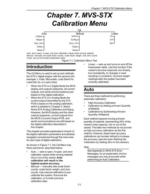
Auto Manual Linear<br />
LoSpan<br />
HiSpan<br />
Zero_Cal<br />
Disply<br />
Reset<br />
ScfCnt<br />
ScfWgt<br />
Zero_Cnt<br />
Disply<br />
Reset<br />
On<br />
Off<br />
Set<br />
Auto: set lo span, hi span, <strong>and</strong> zero calibration values while moving material<br />
Manual: manually set scale factor counts, scale factor weight, <strong>and</strong> zero counts<br />
Linear: set up <strong>and</strong> enable linearization table<br />
Figure 7-1. Calibration Menu Tree<br />
The Cal Menu is used to set up <strong>and</strong> calibrate<br />
the <strong>STX</strong>’s ‘digital engine’ with the sensors (for<br />
example, L-Cells, Microcells, Load St<strong>and</strong> IIs,<br />
Load Disc IIs, or Load Links).<br />
• When the <strong>STX</strong> is in Digital Mode the MVS<br />
display <strong>and</strong> outputs (setpoints, all current<br />
outputs, <strong>and</strong> serial communications) are<br />
based on this digital calibration.<br />
• When the <strong>STX</strong> is in Analog Mode the<br />
current output transmitted by the <strong>STX</strong><br />
PCB is based on the analog calibration,<br />
which is detailed in Chapter 3, St<strong>and</strong>-<br />
Alone <strong>STX</strong> Analog Calibration <strong>and</strong> Setup.<br />
However, the MVS display <strong>and</strong> the other<br />
outputs (setpoints, current outputs from<br />
the MVS’s Current Output PCB, <strong>and</strong><br />
serial communications) are still based on<br />
the digital calibration described in<br />
this chapter.<br />
This chapter provides explanations of each of<br />
the digital calibration parameters <strong>and</strong> detailed<br />
navigation procedures through the menu tree<br />
for each type of digital calibration.<br />
As shown in Figure 7-1, the Cal Menu has<br />
three submenus, described below:<br />
• Auto — sets lo span, hi span, <strong>and</strong> zero<br />
calibration values while moving material<br />
into or out of the vessel. Auto<br />
calibration will result in the<br />
highest system accuracy.<br />
• Manual — manually sets scale factor<br />
counts, scale factor weight, <strong>and</strong> zero<br />
counts. Use manual calibration to precalibrate<br />
the system, fine-tune the<br />
calibration, or re-enter previous<br />
calibration data.<br />
Cal<br />
• Linear — sets up <strong>and</strong> turns on <strong>and</strong> off the<br />
linearization table. Use this function if the<br />
vessel’s structure responds non-linearly,<br />
but consistently, to changes in load,<br />
resulting in consistent, incorrect weight<br />
readings after the system has been<br />
correctly calibrated.<br />
Auto<br />
There are three methods for performing<br />
automatic calibration:<br />
• High-Accuracy Calibration<br />
• Calibration by Adding a Known Quantity<br />
of Material<br />
• Calibration by Subtracting a Known<br />
Quantity of Material<br />
Each method requires moving a known<br />
quantity of material, representing 25% of the<br />
vessel’s total capacity, into or out of the<br />
vessel. The latter two methods do not provide<br />
as high accuracy calibration as the first<br />
method. However, these lower accuracy<br />
calibrations can be later refined to increase<br />
the accuracy (see the topic Refining the<br />
Calibration by Setting Zero in this section).<br />
Note<br />
See Appendix D, MVS-<strong>STX</strong> Error<br />
Messages, for an explanation of error<br />
messages you may encounter while<br />
performing an Auto Calibration.


