

STX Signal Transmitter Installation and Operation ... - Kistler-Morse
STX Signal Transmitter Installation and Operation ... - Kistler-Morse
STX Signal Transmitter Installation and Operation ... - Kistler-Morse

You also want an ePaper? Increase the reach of your titles
YUMPU automatically turns print PDFs into web optimized ePapers that Google loves.
Chapter 8. MVS-<strong>STX</strong> Service Menu<br />
5. Press the Menu Key to display the<br />
menu’s second page. The display shows:<br />
SERVICE ROUTINES<br />
Micro<br />
6. Press the F1 Key to access the Micro<br />
Menu. The display shows:<br />
MICRO FUNCTIONS<br />
7. Press the Menu Key to display the<br />
menu’s second page. The display shows:<br />
MICRO FUNCTIONS<br />
F1 F2 F3<br />
8. Press the F1 Key to access the RScn<br />
Menu. The display shows:<br />
Auto<br />
RE-SCAN MENU<br />
Man<br />
F1 F2 F3<br />
9. Press the F1 Key to access the Auto<br />
Menu. The display shows:<br />
AUTO SCAN MENU<br />
All<br />
i2c_IO<br />
F1 F2 F3<br />
10. To bring on-line slave devices <strong>and</strong><br />
new PCBs, press the F1 Key to access<br />
the All Menu <strong>and</strong> proceed to Steps 11<br />
through 13.<br />
To bring on-line new PCBs only, press<br />
the F3 Key to access the i2c_IO Menu<br />
<strong>and</strong> proceed to Step 14.<br />
11. If you selected All the display shows:<br />
RE-SCAN SYSTEM?<br />
Yes<br />
Access<br />
F1 F2 F3<br />
IDrst KeyT Prnt<br />
F1 F2 F3<br />
RScn RsRAM Stdr<br />
12. Press the F1 Key to select Yes. The MVS<br />
scans the entire network <strong>and</strong> brings online<br />
the slave devices <strong>and</strong> new PCBs.<br />
When the MVS is through scanning it<br />
displays the following:<br />
XX SIGNAL<br />
No<br />
F1 F2 F3<br />
PROCESSORS FOUND<br />
F1 F2 F3<br />
The actual number of signal processing<br />
channels displays in place of ‘XX.’ Note<br />
that math channels are not considered<br />
signal processing channels.<br />
13. Press the Esc Key to scroll up the menu<br />
tree or press the Auto/Man Key to return to<br />
channel monitoring. The remaining steps<br />
deal with rescanning the I 2 C only.<br />
14. If you selected i2c_IO in Step 10 the<br />
display shows:<br />
RE-SCAN I2C BUS?<br />
Yes<br />
15. Press the F1 Key to select Yes. The MVS<br />
scans the entire network <strong>and</strong> brings on-line<br />
any new PCBs. The display returns to:<br />
RE-SCAN MENU<br />
Auto<br />
Man<br />
F1 F2 F3<br />
16. Press the Esc Key to scroll up the menu<br />
tree or press the Auto/Man Key to return to<br />
channel monitoring.<br />
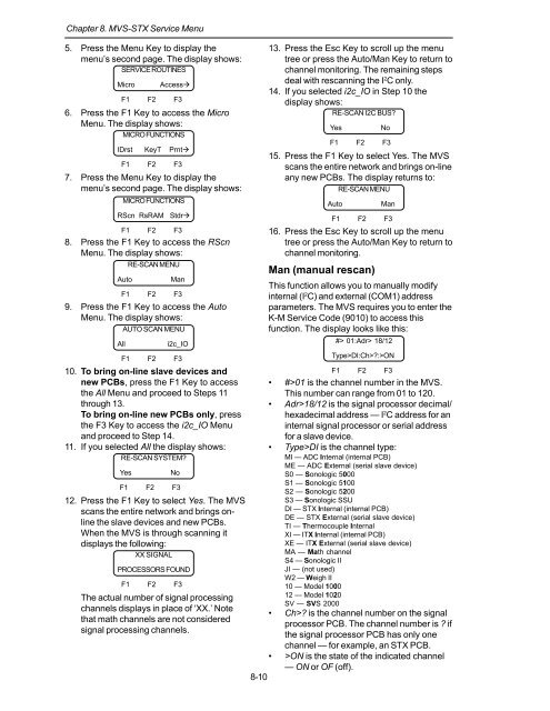
Man (manual rescan)<br />
This function allows you to manually modify<br />
internal (I 2 C) <strong>and</strong> external (COM1) address<br />
parameters. The MVS requires you to enter the<br />
K-M Service Code (9010) to access this<br />
function. The display looks like this:<br />
F1 F2 F3<br />
• #>01 is the channel number in the MVS.<br />
This number can range from 01 to 120.<br />
• Adr>18/12 is the signal processor decimal/<br />
hexadecimal address — I 2 C address for an<br />
internal signal processor or serial address<br />
for a slave device.<br />
• Type>DI is the channel type:<br />
MI — ADC Internal (internal PCB)<br />
ME — ADC External (serial slave device)<br />
S0 — Sonologic 5000<br />
S1 — Sonologic 5100<br />
S2 — Sonologic 5200<br />
S3 — Sonologic SSU<br />
DI — <strong>STX</strong> Internal (internal PCB)<br />
DE — <strong>STX</strong> External (serial slave device)<br />
TI — Thermocouple Internal<br />
XI — ITX Internal (internal PCB)<br />
XE — ITX External (serial slave device)<br />
MA — Math channel<br />
S4 — Sonologic II<br />
JI — (not used)<br />
W2 — Weigh II<br />
10 — Model 1000<br />
12 — Model 1020<br />
SV — SVS 2000<br />
• Ch>? is the channel number on the signal<br />
processor PCB. The channel number is ? if<br />
the signal processor PCB has only one<br />
channel — for example, an <strong>STX</strong> PCB.<br />
• >ON is the state of the indicated channel<br />
— ON or OF (off).<br />
8-10<br />
No<br />
F1 F2 F3<br />
#> 01:Adr> 18/12<br />
Type>DI:Ch>?:>ON


