

STX Signal Transmitter Installation and Operation ... - Kistler-Morse
STX Signal Transmitter Installation and Operation ... - Kistler-Morse
STX Signal Transmitter Installation and Operation ... - Kistler-Morse

You also want an ePaper? Increase the reach of your titles
YUMPU automatically turns print PDFs into web optimized ePapers that Google loves.
Chapter 8. MVS-<strong>STX</strong> Service Menu<br />
K-M Service Code<br />
The K-M Service Code is required to change<br />
some parameters within the Service Menu<br />
unless you entered the K-M Mfg Code. The<br />
Service Code is:<br />
9010<br />
You can view parameters in the Service Menu<br />
without entering the Service Code, but will be<br />
prompted to enter the Code if you try to<br />
change certain parameters. Once the Service<br />
Code is entered, you have access to all<br />
functions that require the Code, while you<br />
remain within the Manual Mode. You only<br />
need to enter the Code once per Manual<br />
Mode session, regardless of the number of<br />
functions <strong>and</strong> channels you access.<br />
<strong>STX</strong><br />
This menu is used to:<br />
• display material weight <strong>and</strong> A/D counts<br />
• download calibration information to a new<br />
<strong>STX</strong> PCB or microprocessor PCB<br />
• enable or disable monitoring for a channel<br />
• adjust excitation<br />
• reset the <strong>STX</strong> PCB to default parameters<br />
• adjust resolution, gain, <strong>and</strong> active digits<br />
• set (or reset) channel default parameters<br />
• select analog or digital mode<br />
• set up <strong>and</strong> enable filtering <strong>and</strong> tracking<br />
parameters to reduce the effects of<br />
‘noise’ <strong>and</strong> drift<br />
Descriptions of the submenus follow.<br />
Disp (display)<br />
This function displays material weight, ‘raw’<br />
<strong>and</strong> ‘corrected’ A/D counts, <strong>and</strong> stability.<br />
‘Corrected’ counts are calculated after all<br />
corrections, such as averaging <strong>and</strong> linearization,<br />
are applied. ‘Raw’ counts are the counts<br />
before any corrections are applied.<br />
The first page of the display looks like this:<br />
01: 1043962 Cts<br />
Ad12:<br />
1250 lbs<br />
F1 F2 F3<br />
• 01 is the factory-set channel ID<br />
• 1043962 Cts is the ‘corrected’ counts<br />
• 12 is the <strong>STX</strong> PCB’s hexadecimal<br />
address — first rack (‘1’), second<br />
position in rack (‘2’)<br />
• 1250 lbs is the current material weight<br />
8-2<br />
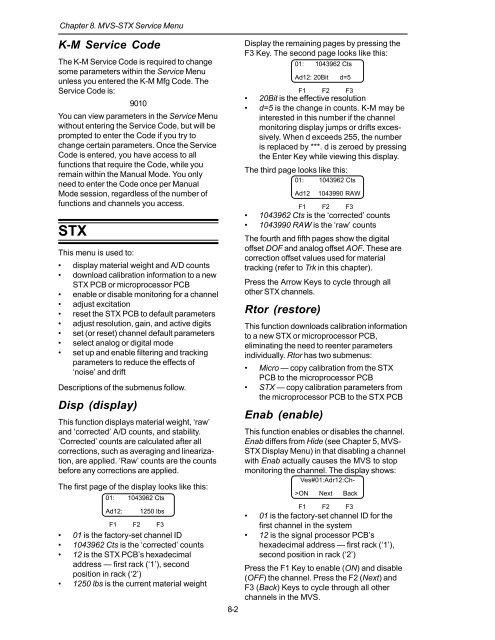
Display the remaining pages by pressing the<br />
F3 Key. The second page looks like this:<br />
01: 1043962 Cts<br />
F1 F2 F3<br />
• 20Bit is the effective resolution<br />
• d=5 is the change in counts. K-M may be<br />
interested in this number if the channel<br />
monitoring display jumps or drifts excessively.<br />
When d exceeds 255, the number<br />
is replaced by ***. d is zeroed by pressing<br />
the Enter Key while viewing this display.<br />
The third page looks like this:<br />
01: 1043962 Cts<br />
F1 F2 F3<br />
• 1043962 Cts is the ‘corrected’ counts<br />
• 1043990 RAW is the ‘raw’ counts<br />
The fourth <strong>and</strong> fifth pages show the digital<br />
offset DOF <strong>and</strong> analog offset AOF. These are<br />
correction offset values used for material<br />
tracking (refer to Trk in this chapter).<br />
Press the Arrow Keys to cycle through all<br />
other <strong>STX</strong> channels.<br />
Rtor (restore)<br />
Ad12: 20Bit d=5<br />
Ad12<br />
This function downloads calibration information<br />
to a new <strong>STX</strong> or microprocessor PCB,<br />
eliminating the need to reenter parameters<br />
individually. Rtor has two submenus:<br />
• Micro — copy calibration from the <strong>STX</strong><br />
PCB to the microprocessor PCB<br />
• <strong>STX</strong> — copy calibration parameters from<br />
the microprocessor PCB to the <strong>STX</strong> PCB<br />
Enab (enable)<br />
1043990 RAW<br />
This function enables or disables the channel.<br />
Enab differs from Hide (see Chapter 5, MVS-<br />
<strong>STX</strong> Display Menu) in that disabling a channel<br />
with Enab actually causes the MVS to stop<br />
monitoring the channel. The display shows:<br />
Ves#01:Adr12:Ch-<br />
>ON Next Back<br />
F1 F2 F3<br />
• 01 is the factory-set channel ID for the<br />
first channel in the system<br />
• 12 is the signal processor PCB’s<br />
hexadecimal address — first rack (‘1’),<br />
second position in rack (‘2’)<br />
Press the F1 Key to enable (ON) <strong>and</strong> disable<br />
(OFF) the channel. Press the F2 (Next) <strong>and</strong><br />
F3 (Back) Keys to cycle through all other<br />
channels in the MVS.


