

STX Signal Transmitter Installation and Operation ... - Kistler-Morse
STX Signal Transmitter Installation and Operation ... - Kistler-Morse
STX Signal Transmitter Installation and Operation ... - Kistler-Morse

You also want an ePaper? Increase the reach of your titles
YUMPU automatically turns print PDFs into web optimized ePapers that Google loves.
Chapter 6. MVS-<strong>STX</strong> Inputs <strong>and</strong> Outputs Menu<br />
ADDR (address)<br />
External equipment may have many signal<br />
processors daisy chain wired to it. The signal<br />
processor base address identifies the signal<br />
processor <strong>and</strong> associated channels to the<br />
external equipment. Each device on the same<br />
serial connection must have a different base<br />
address. The base address of the MVS’s<br />
COM port is set up in the ADDR Menu. The<br />
base address can be expressed in two ways<br />
— decimal form (ranging from 0 to 255) <strong>and</strong><br />
hexadecimal form (ranging from 0 to FF).<br />
The default is 01 in decimal form (01 in<br />
hexadecimal form).<br />
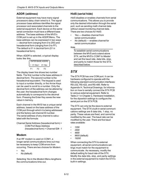
When ADDR is selected, a typical display<br />
looks like this:<br />
ENTER BASE ADDRS<br />
> 01 Dec= 01 Hex<br />
F1 F2 F3<br />
The display lower line shows two number<br />
fields. The first number is the base address in<br />
decimal form. The second number is the<br />
hexadecimal equivalent. The keypad is used<br />
to input a number directly, or the Arrow Keys<br />
can be used to scroll to a number. Only the<br />
decimal form of the address can be altered by<br />
the user; the hexadecimal form changes<br />
automatically to correspond to the decimal<br />
form. Pressing the Enter Key saves the new<br />
value in memory.<br />
Each channel in the MVS has a unique serial<br />
address, based on the base address of the<br />
COM port through which it is being addressed<br />
<strong>and</strong> the factory-set channel ID number.<br />
The serial address of any channel is calculated<br />
with the formula:<br />
Channel Serial Address (hexadecimal form) =<br />
COM Port Base Address<br />
(hexadecimal form) + Channel ID# - 1<br />
Modem<br />
If an RF modem is used on COM1, a<br />
longer serial communications time-out may<br />
be necessary to keep COM errors from<br />
occurring. There are two choices for Modem:<br />
• Yes<br />
• No (default)<br />
Selecting Yes in the Modem Menu lengthens<br />
the communications time-out.<br />
HidS (serial hide)<br />
HidS disables or enables channels from serial<br />
communications. This allows you to provide<br />
only the desired information through the serial<br />
port, such as sending math channel data<br />
without vessel monitoring channel data.<br />
There are two choices for HidS:<br />
• Yes — disables channel from<br />
serial communication<br />
• No (default) — enables channel for<br />
serial communication<br />
Note<br />
To establish serial communications<br />
between the MVS <strong>and</strong> a st<strong>and</strong>-alone<br />
<strong>STX</strong>, set the MVS’s COM1 to Master<br />
<strong>and</strong> set the baud rate, data bits, stop,<br />
<strong>and</strong> parity to match those for the <strong>STX</strong>,<br />
described below.<br />
<strong>STX</strong><br />
The <strong>STX</strong> PCB has one COM port. It can be<br />
hardware configured to operate with the<br />
following st<strong>and</strong>ard communication interfaces:<br />
RS-232, RS-422, <strong>and</strong> RS-485. Refer to<br />
Appendix H, Technical Drawings, for information<br />
on how to serially connect the <strong>STX</strong> PCB<br />
to various external equipment. Refer to<br />
Table 2-1 in Chapter 2, Hardware <strong>Installation</strong>,<br />
for the dipswitch settings to configure the<br />
serial port on the <strong>STX</strong> PCB.<br />
The <strong>STX</strong> can only be the slave to external<br />
equipment. The <strong>STX</strong>’s built-in serial communications<br />
settings are 8 data bits, 1 stop, no<br />
parity. These values are fixed, <strong>and</strong> cannot be<br />
modified by the user. The baud rate can be<br />
modified by the user. There are five baud<br />
rates available:<br />
• 1200<br />
• 2400<br />
• 4800<br />
• 9600 (default)<br />
• 19200<br />
When connecting the <strong>STX</strong> to external<br />
equipment, all serial communications settings<br />
must match for the equipment to<br />
communicate. As necessary, modify the<br />
default setting for baud rate of the <strong>STX</strong>.<br />
Modify the data bits, stop, <strong>and</strong> parity settings<br />
in the external equipment to match the <strong>STX</strong>’s<br />
built-in settings.<br />
6-12


