

STX Signal Transmitter Installation and Operation ... - Kistler-Morse
STX Signal Transmitter Installation and Operation ... - Kistler-Morse
STX Signal Transmitter Installation and Operation ... - Kistler-Morse

You also want an ePaper? Increase the reach of your titles
YUMPU automatically turns print PDFs into web optimized ePapers that Google loves.
Chapter 8. MVS-<strong>STX</strong> Service Menu<br />
Deflt (default)<br />
This function is used to:<br />
• reset Gain, Res, <strong>and</strong> Digt for the <strong>STX</strong> to<br />
factory-set default values, or<br />
• set default values for Gain, Res, <strong>and</strong> Digt<br />
if you add an <strong>STX</strong> PCB to an MVS or<br />
add serial communications for an <strong>STX</strong><br />
to the MVS.<br />
The defaults for gain, resolution, <strong>and</strong> active<br />
digits vary, depending on sensor type. Deflt<br />
selections <strong>and</strong> corresponding values are<br />
shown in Table 8-3.<br />
Gain Res (bits) Digt<br />
MC4 2 20 4<br />
DS4 4 20 4<br />
DS5 4 21 5<br />
FG5 32 21 5<br />
FG6 64 21 6<br />
Legend:<br />
MC=K-M Microcells or L-Cells<br />
DS=K-M direct support Load St<strong>and</strong> II, Load Disc II, or<br />
Load Link I <strong>and</strong> II<br />
FG=full bridge, foil gage sensors<br />
Table 8-3. Default Values<br />
Mode<br />
This function selects the operation mode —<br />
Analog or Digtal (digital). In analog mode, the<br />
<strong>STX</strong> PCB’s current output is controlled by the<br />
‘analog engine,’ calibrated with switches on<br />
the PCB. In digital mode, the <strong>STX</strong> PCB’s<br />
current output is controlled by the ‘digital<br />
engine,’ calibrated using the MVS menu tree.<br />
The default is Analog. The selection for Mode<br />
applies only to the current channel.<br />
Filter<br />
Vibrations in a vessel can cause changes in<br />
the weight display <strong>and</strong> outputs, even though<br />
no material is moved, because the vibrations<br />
affect the vessel’s structural response. The<br />
Sentry Filter reduces display <strong>and</strong> output<br />
changes that can result from vibration. The<br />
principle behind the filtering follows.<br />
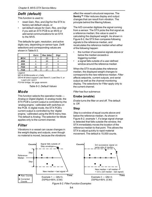
The A/D converter digitizes the signal coming<br />
from a sensor. The <strong>STX</strong> picks the first signal as<br />
a reference median; this value is used in<br />
calculating the displayed weight. As shown in<br />
Figure 8-2, the <strong>STX</strong> then compares following<br />
signals to the reference median, <strong>and</strong><br />
recalculates the reference median when either<br />
of the following happen:<br />
• the number of successive signals above or<br />
below the median exceeds a<br />
triggering number<br />
• a signal falls outside of a user-defined<br />
window around the reference median<br />
When the <strong>STX</strong> recalculates the reference<br />
median, the displayed weight changes to<br />
correspond to the new reference median. Filter<br />
affects setpoints, current outputs, <strong>and</strong> serial<br />
output as well as the channel monitoring<br />
display. The selections for Filter apply only to<br />
the current channel.<br />
Filter has four submenus:<br />
Enabe (enable)<br />
Enabe turns the filter on <strong>and</strong> off. The default<br />
is Off.<br />
Step<br />
Step is a window of equal counts above <strong>and</strong><br />
below the reference median. As shown in<br />
Figure 8-2, example 1, if a large signal change<br />
is detected that falls outside the window, the<br />
<strong>STX</strong> immediately moves the location of the<br />
reference median to that point. This allows the<br />
<strong>STX</strong> to adjust quickly to rapid material<br />
movement. The default is 15,000 counts.<br />
Counts<br />
<strong>Signal</strong> falls outside of<br />
Step envelope<br />
Counts<br />
3rd successive signal on<br />
same side of median<br />
Reference<br />
Median<br />
Step<br />
Step<br />
New median = last signal<br />
New median = ref median<br />
+ 0.8 x (ref median - last signal)<br />
Raw Counts<br />
Corrected<br />
Counts<br />
Example 1 — Qlfy=3,<br />
DSPfact=80% (0.80)<br />
Time<br />
Figure 8-2. Filter Function Examples<br />
8-4<br />
Example 2 — Qlfy=3,<br />
DSPfact=80% (0.80)<br />
Time


