STX Signal Transmitter Installation and Operation ... - Kistler-Morse
STX Signal Transmitter Installation and Operation ... - Kistler-Morse
STX Signal Transmitter Installation and Operation ... - Kistler-Morse
You also want an ePaper? Increase the reach of your titles
YUMPU automatically turns print PDFs into web optimized ePapers that Google loves.
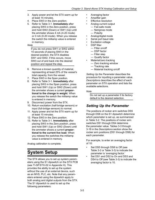
Chapter 3. St<strong>and</strong>-Alone <strong>STX</strong> Analog Calibration <strong>and</strong> Setup<br />
3. Apply power <strong>and</strong> let the <strong>STX</strong> warm up for<br />
at least 15 minutes.<br />
4. Place SW3 in the Zero position.<br />
5. Refer to Table 3-1. Immediately after<br />
placing SW3 in the Zero position, press<br />
<strong>and</strong> hold SW2 (Down) or SW1 (Up) until<br />
the ammeter shows 4 mA (4-20 mode)<br />
or 0 mA (0-20 mode). When you release<br />
the switch the milliamp value is entered<br />
in memory.<br />
Note<br />
If you do not press SW1 or SW2 within<br />
15 seconds of placing SW3 in the<br />
desired position, the <strong>STX</strong> disables<br />
SW1 <strong>and</strong> SW2. If this occurs, move<br />
SW3 out of <strong>and</strong> back into the desired<br />
position <strong>and</strong> repeat the step.<br />
6. Remove a known quantity of material,<br />
representing at least 25% of the vessel’s<br />
total capacity, from the vessel.<br />
7. Place SW3 in the Span position.<br />
8. Refer to Table 3-1. Immediately after<br />
placing SW3 in the Span position, press<br />
<strong>and</strong> hold SW1 (Up) or SW2 (Down) until<br />
the ammeter shows a current proportional<br />
to the change in weight. When<br />
you release the switch the milliamp value<br />
is entered in memory.<br />
9. Disconnect power from the <strong>STX</strong>.<br />
10. Return excitation (half-bridge sensors) or<br />
input (full-bridge sensors) to normal.<br />
11. Apply power <strong>and</strong> let the <strong>STX</strong> warm up for<br />
at least 15 minutes.<br />
12. Place SW3 in the Zero position.<br />
13. Refer to Table 3-1. Immediately after<br />
placing SW3 in the Zero position, press<br />
<strong>and</strong> hold SW1 (Up) or SW2 (Down) until<br />
the ammeter shows a current proportional<br />
to the current live load. When<br />
you release the switches the milliamp<br />
value is entered in memory.<br />
Analog calibration is complete.<br />
System Setup<br />
The <strong>STX</strong> allows you to set up system parameters<br />
using the S1 dipswitch on the <strong>STX</strong> PCB<br />
(see TI-SP.<strong>STX</strong>-02 in Appendix H). This<br />
provides the ability to set up the system<br />
without the use of an external device, such<br />
as an MVS, PLC, etc. Note that any parameters<br />
entered using the dipswitch apply to<br />
both analog <strong>and</strong> digital outputs from the <strong>STX</strong>.<br />
The S1 dipswitch is used to set up the<br />
following parameters:<br />
3-5<br />
• Averaging factor<br />
• Amplifier gain<br />
• Effective resolution<br />
• Analog current output<br />
— Fail-safe mode<br />
— Net/gross mode<br />
— Polarity<br />
• Analog/digital mode<br />
• Serial port baud rate<br />
• Excitation voltage<br />
• DSP filter<br />
— Filter on/off<br />
— DSP factor<br />
— Filter step<br />
— Qualify factor<br />
• Material/zero tracking<br />
— Zero tracking window<br />
— Tracking rate<br />
— Material tracking on/off<br />
Setting Up the Parameter describes the<br />
procedure for inputting a parameter value.<br />
Descriptions describes the effect of each<br />
parameter on <strong>STX</strong> operation <strong>and</strong> lists the<br />
available selections.<br />
Note<br />
Do not set up a parameter if its factory<br />
default is the desired selection.<br />
Setting Up the Parameter<br />
The positions of rocker arm switches DS5<br />
through DS8 on the S1 dipswitch determine<br />
which parameter is set up, as summarized<br />
in Table 3-2. The positions of rocker arm<br />
switches DS1 through DS4 determine<br />
the parameter value. Tables 3-3 through<br />
3-18 in the Descriptions section show the<br />
rocker arm positions (DS1 through DS8) for<br />
each parameter.<br />
For example, to enter an averaging factor<br />
of 10:<br />
• Set DS5 through DS8 to Off (see<br />
Table 3-2 or Table 3-3) to indicate the<br />
parameter is ‘averaging factor.’<br />
• Set DS1 <strong>and</strong> DS2 to On <strong>and</strong> DS3 <strong>and</strong><br />
DS4 to Off (see Table 3-3) to indicate the<br />
averaging factor is 10.


