

STX Signal Transmitter Installation and Operation ... - Kistler-Morse
STX Signal Transmitter Installation and Operation ... - Kistler-Morse
STX Signal Transmitter Installation and Operation ... - Kistler-Morse

You also want an ePaper? Increase the reach of your titles
YUMPU automatically turns print PDFs into web optimized ePapers that Google loves.
Chapter 8. MVS-<strong>STX</strong> Service Menu<br />
E2rst (EEPROM reset)<br />
(MVS only; does not apply to current<br />
output on <strong>STX</strong> PCB)<br />
This function resets the current output Mode<br />
<strong>and</strong> the Iadj tuning parameters for 0 mA,<br />
4 mA, <strong>and</strong> 20 mA to default values for all<br />
channels on the displayed Current Output<br />
PCB. The E2rst display looks like this:<br />
DEFAULT ADDR 15?<br />
F1 F2 F3<br />
ADDR 15 is the Current Output PCB’s<br />
hexadecimal address.<br />
Press the F1 Key to default the current<br />
output parameters for all channels on the<br />
displayed Current Output PCB to:<br />
• Mode — 4-20 mA<br />
• Calibration values —<br />
20 mA value =14329 counts<br />
4 mA value = 3738 counts<br />
0 mA value = 1096 counts<br />
The display flashes a message acknowledging<br />
the entry. Pressing the F3 Key exits the<br />
menu without defaulting.<br />
If there are multiple Current Output PCBs, the<br />
MVS advances to the address of the next<br />
Current Output PCB.<br />
Test<br />
Yes<br />
No<br />
This function allows manual activation of<br />
current output channels outside of normal<br />
control. The system issues a warning that<br />
automatic control of current outputs assigned<br />
to the selected channel is transferred to<br />
manual control, <strong>and</strong> requests verification.<br />
CAUTION<br />
Manually activating current output can<br />
cause damage if control equipment is<br />
connected. Disconnect control equipment<br />
before proceeding.<br />
MVS Menu<br />
After the warning message, if more than one<br />
current output has been assigned for this<br />
channel, a selection of the two current output<br />
channels is offered. After you select a<br />
channel, a Test display looks like this:<br />
Iout01 :AD 15:Ch1<br />
• Iout01 <strong>and</strong> Ch1 is the channel number on<br />
the Current Output PCB. Each Current<br />
Output PCB has eight multiplexed<br />
current output channels.<br />
• Ad 15 is the Current Output PCB’s<br />
hexadecimal address.<br />
• 04mA is the current sent to the current<br />
output channel being tested. If the current<br />
mode is 0-20mA, the test current output<br />
ranges from 0 mA to 20 mA in 2 mA<br />
steps. If in the 4-20mA mode, the test<br />
current output ranges from 4 mA to<br />
20 mA in 2 mA steps.<br />
• More or Less refers to the increase<br />
(More) or decrease (Less) of the output.<br />
Press the F2 Key to increase output in<br />
2 mA steps. Press the F3 Key to<br />
decrease output in 2 mA steps.<br />
Press the Esc or Auto/Man Key to terminate<br />
the test. Once the test is terminated, the<br />
current output returns to automatic control.<br />
To test current output for another channel<br />
assigned to this <strong>STX</strong> channel on the Current<br />
Output PCB, select Test again <strong>and</strong> then<br />
select the other current output channel.<br />
<strong>STX</strong> Menu<br />
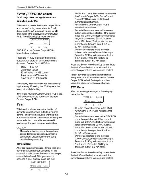
After the warning message, a Test display<br />
looks like this:<br />
TEST 01 Addr 12<br />
>04ma: More<br />
Less<br />
F1 F2 F3<br />
• 01 is the channel number in the MVS.<br />
• Ad 12 is the <strong>STX</strong> PCB’s hexadecimal<br />
address.<br />
• 04mA is the current sent to the <strong>STX</strong> PCB<br />
current output channel. If the current<br />
mode is 0-20mA, the test current output<br />
ranges from 0 mA to 20 mA in 2 mA<br />
steps. If in the 4-20mA mode, the test<br />
current output ranges from 4 mA to<br />
20 mA in 2 mA steps.<br />
• More or Less refers to the increase<br />
(More) or decrease (Less) of the output.<br />
Press the F2 Key to increase output in<br />
2 mA steps. Press the F3 Key to<br />
decrease output in 2 mA steps.<br />
Press the Esc or Auto/Man Key to terminate<br />
the test. Once the test is terminated, the<br />
current output returns to automatic control.<br />
>04ma: More<br />
Less<br />
F1 F2 F3<br />
8-8


