

STX Signal Transmitter Installation and Operation ... - Kistler-Morse
STX Signal Transmitter Installation and Operation ... - Kistler-Morse
STX Signal Transmitter Installation and Operation ... - Kistler-Morse

Create successful ePaper yourself
Turn your PDF publications into a flip-book with our unique Google optimized e-Paper software.
Chapter 6. MVS-<strong>STX</strong> Inputs <strong>and</strong> Outputs Menu<br />
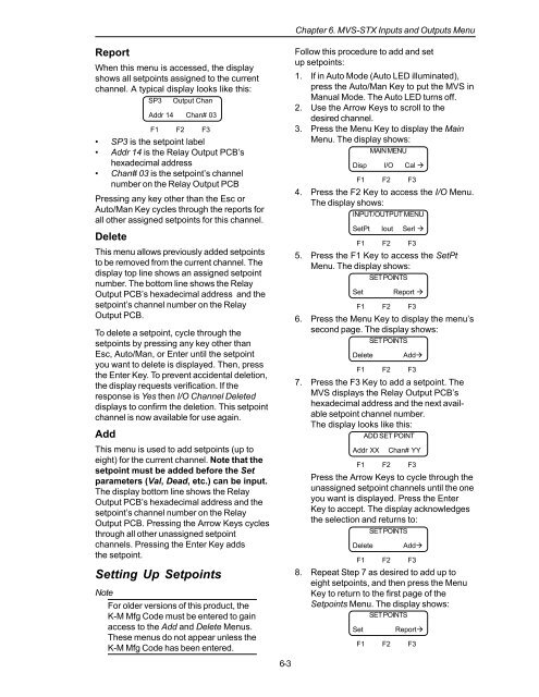
Report<br />
When this menu is accessed, the display<br />
shows all setpoints assigned to the current<br />
channel. A typical display looks like this:<br />
SP3 Output Chan<br />
Addr 14 Chan# 03<br />
F1 F2 F3<br />
• SP3 is the setpoint label<br />
• Addr 14 is the Relay Output PCB’s<br />
hexadecimal address<br />
• Chan# 03 is the setpoint’s channel<br />
number on the Relay Output PCB<br />
Pressing any key other than the Esc or<br />
Auto/Man Key cycles through the reports for<br />
all other assigned setpoints for this channel.<br />
Delete<br />
This menu allows previously added setpoints<br />
to be removed from the current channel. The<br />
display top line shows an assigned setpoint<br />
number. The bottom line shows the Relay<br />
Output PCB’s hexadecimal address <strong>and</strong> the<br />
setpoint’s channel number on the Relay<br />
Output PCB.<br />
To delete a setpoint, cycle through the<br />
setpoints by pressing any key other than<br />
Esc, Auto/Man, or Enter until the setpoint<br />
you want to delete is displayed. Then, press<br />
the Enter Key. To prevent accidental deletion,<br />
the display requests verification. If the<br />
response is Yes then I/O Channel Deleted<br />
displays to confirm the deletion. This setpoint<br />
channel is now available for use again.<br />
Add<br />
This menu is used to add setpoints (up to<br />
eight) for the current channel. Note that the<br />
setpoint must be added before the Set<br />
parameters (Val, Dead, etc.) can be input.<br />
The display bottom line shows the Relay<br />
Output PCB’s hexadecimal address <strong>and</strong> the<br />
setpoint’s channel number on the Relay<br />
Output PCB. Pressing the Arrow Keys cycles<br />
through all other unassigned setpoint<br />
channels. Pressing the Enter Key adds<br />
the setpoint.<br />
Setting Up Setpoints<br />
Note<br />
For older versions of this product, the<br />
K-M Mfg Code must be entered to gain<br />
access to the Add <strong>and</strong> Delete Menus.<br />
These menus do not appear unless the<br />
K-M Mfg Code has been entered.<br />
6-3<br />
Follow this procedure to add <strong>and</strong> set<br />
up setpoints:<br />
1. If in Auto Mode (Auto LED illuminated),<br />
press the Auto/Man Key to put the MVS in<br />
Manual Mode. The Auto LED turns off.<br />
2. Use the Arrow Keys to scroll to the<br />
desired channel.<br />
3. Press the Menu Key to display the Main<br />
Menu. The display shows:<br />
MAIN MENU<br />
Disp I/O Cal <br />
F1 F2 F3<br />
4. Press the F2 Key to access the I/O Menu.<br />
The display shows:<br />
INPUT/OUTPUT MENU<br />
SetPt Iout Serl <br />
F1 F2 F3<br />
5. Press the F1 Key to access the SetPt<br />
Menu. The display shows:<br />
SET POINTS<br />
Set<br />
Report <br />
F1 F2 F3<br />
6. Press the Menu Key to display the menu’s<br />
second page. The display shows:<br />
SET POINTS<br />
Delete<br />
Add<br />
F1 F2 F3<br />
7. Press the F3 Key to add a setpoint. The<br />
MVS displays the Relay Output PCB’s<br />
hexadecimal address <strong>and</strong> the next available<br />
setpoint channel number.<br />
The display looks like this:<br />
ADD SET POINT<br />
Addr XX<br />
Chan# YY<br />
F1 F2 F3<br />
Press the Arrow Keys to cycle through the<br />
unassigned setpoint channels until the one<br />
you want is displayed. Press the Enter<br />
Key to accept. The display acknowledges<br />
the selection <strong>and</strong> returns to:<br />
SET POINTS<br />
Delete<br />
Add<br />
F1 F2 F3<br />
8. Repeat Step 7 as desired to add up to<br />
eight setpoints, <strong>and</strong> then press the Menu<br />
Key to return to the first page of the<br />
Setpoints Menu. The display shows:<br />
SET POINTS<br />
Set<br />
Report<br />
F1 F2 F3


