STX Signal Transmitter Installation and Operation ... - Kistler-Morse
STX Signal Transmitter Installation and Operation ... - Kistler-Morse
STX Signal Transmitter Installation and Operation ... - Kistler-Morse
Create successful ePaper yourself
Turn your PDF publications into a flip-book with our unique Google optimized e-Paper software.
Chapter 1. Introduction<br />
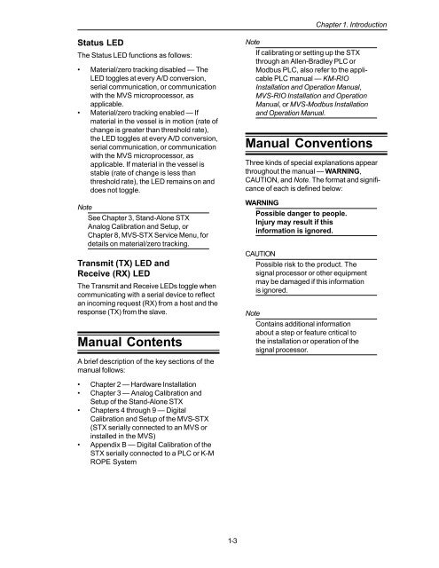
Status LED<br />
The Status LED functions as follows:<br />
• Material/zero tracking disabled — The<br />
LED toggles at every A/D conversion,<br />
serial communication, or communication<br />
with the MVS microprocessor, as<br />
applicable.<br />
• Material/zero tracking enabled — If<br />
material in the vessel is in motion (rate of<br />
change is greater than threshold rate),<br />
the LED toggles at every A/D conversion,<br />
serial communication, or communication<br />
with the MVS microprocessor, as<br />
applicable. If material in the vessel is<br />
stable (rate of change is less than<br />
threshold rate), the LED remains on <strong>and</strong><br />
does not toggle.<br />
Note<br />
See Chapter 3, St<strong>and</strong>-Alone <strong>STX</strong><br />
Analog Calibration <strong>and</strong> Setup, or<br />
Chapter 8, MVS-<strong>STX</strong> Service Menu, for<br />
details on material/zero tracking.<br />
Transmit (TX) LED <strong>and</strong><br />
Receive (RX) LED<br />
The Transmit <strong>and</strong> Receive LEDs toggle when<br />
communicating with a serial device to reflect<br />
an incoming request (RX) from a host <strong>and</strong> the<br />
response (TX) from the slave.<br />
Manual Contents<br />
A brief description of the key sections of the<br />
manual follows:<br />
Note<br />
If calibrating or setting up the <strong>STX</strong><br />
through an Allen-Bradley PLC or<br />
Modbus PLC, also refer to the applicable<br />
PLC manual — KM-RIO<br />
<strong>Installation</strong> <strong>and</strong> <strong>Operation</strong> Manual,<br />
MVS-RIO <strong>Installation</strong> <strong>and</strong> <strong>Operation</strong><br />
Manual, or MVS-Modbus <strong>Installation</strong><br />
<strong>and</strong> <strong>Operation</strong> Manual.<br />
Manual Conventions<br />
Three kinds of special explanations appear<br />
throughout the manual — WARNING,<br />
CAUTION, <strong>and</strong> Note. The format <strong>and</strong> significance<br />
of each is defined below:<br />
WARNING<br />
Possible danger to people.<br />
Injury may result if this<br />
information is ignored.<br />
CAUTION<br />
Possible risk to the product. The<br />
signal processor or other equipment<br />
may be damaged if this information<br />
is ignored.<br />
Note<br />
Contains additional information<br />
about a step or feature critical to<br />
the installation or operation of the<br />
signal processor.<br />
• Chapter 2 — Hardware <strong>Installation</strong><br />
• Chapter 3 — Analog Calibration <strong>and</strong><br />
Setup of the St<strong>and</strong>-Alone <strong>STX</strong><br />
• Chapters 4 through 9 — Digital<br />
Calibration <strong>and</strong> Setup of the MVS-<strong>STX</strong><br />
(<strong>STX</strong> serially connected to an MVS or<br />
installed in the MVS)<br />
• Appendix B — Digital Calibration of the<br />
<strong>STX</strong> serially connected to a PLC or K-M<br />
ROPE System<br />
1-3


