- Page 2:
Editor Associate Editor for Gynecol
- Page 6:
Editor Dev Maulik, MD, Ph.D. Winthr
- Page 10:
Preface It is with great pleasure w
- Page 16:
Contents 1 Doppler Sonography: A Br
- Page 20:
a Contents XIII Heart and Great Ves
- Page 24:
a Contents XV 15 Pulsed Doppler Ult
- Page 28:
a Contents XVII 22 Doppler Velocime
- Page 32:
a Contents XIX Clinical Application
- Page 36:
a Contents XXI Terbutaline ........
- Page 42: XXIV Authors Torvid Kiserud, MD, Ph
- Page 46: 2 D. Maulik Fig. 1.2. Title page of
- Page 50: 4 D. Maulik Fig. 1.4. Model of the
- Page 54: 6 D. Maulik Table 1.1. Feasibility
- Page 60: Chapter 2 Physical Principles of Do
- Page 64: a Chapter 2 Physical Principles of
- Page 68: a Chapter 2 Physical Principles of
- Page 72: a Chapter 2 Physical Principles of
- Page 76: a Chapter 2 Physical Principles of
- Page 82: 20 D. Maulik one-fourth of a cycle
- Page 86: 22 D. Maulik arterial [6] hemodynam
- Page 90: 24 D. Maulik nomena. The autoregres
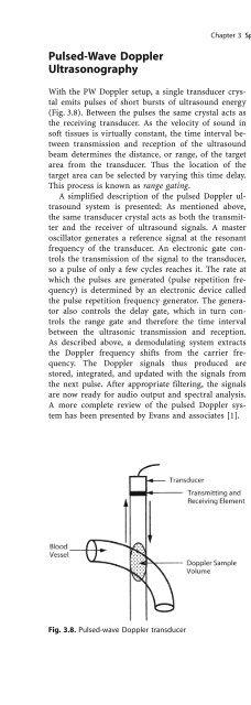
- Page 96: a Chapter 3 Spectral Doppler: Basic
- Page 100: a Chapter 3 Spectral Doppler: Basic
- Page 104: a Chapter 3 Spectral Doppler: Basic
- Page 108: a Chapter 3 Spectral Doppler: Basic
- Page 112: Chapter 4 Spectral Doppler Sonograp
- Page 116: a Chapter 4 Spectral Doppler Sonogr
- Page 120: a Chapter 4 Spectral Doppler Sonogr
- Page 124: a Chapter 4 Spectral Doppler Sonogr
- Page 128: a Chapter 4 Spectral Doppler Sonogr
- Page 132: is inherent in its formuation and i
- Page 136: a Chapter 4 Spectral Doppler Sonogr
- Page 140: a Chapter 4 Spectral Doppler Sonogr
- Page 144:
a Chapter 4 Spectral Doppler Sonogr
- Page 148:
a Chapter 4 Spectral Doppler Sonogr
- Page 152:
a Chapter 4 Spectral Doppler Sonogr
- Page 156:
Chapter 5 Venous Hemodynamics Torvi
- Page 160:
a Chapter 5 Venous Hemodynamics 59
- Page 164:
a Chapter 5 Venous Hemodynamics 61
- Page 168:
a Chapter 5 Venous Hemodynamics 63
- Page 172:
a Chapter 5 Venous Hemodynamics 65
- Page 176:
a Chapter 5 Venous Hemodynamics 67
- Page 182:
70 D. Maulik scan line is timed acc
- Page 186:
72 D. Maulik 1. Transducer for tran
- Page 190:
74 D. Maulik and its location can b
- Page 194:
76 D. Maulik Fig. 6.6. Color M-mode
- Page 198:
78 D. Maulik Fig. 6.8a±d. Doppler
- Page 202:
80 D. Maulik terval as to cause ran
- Page 206:
82 D. Maulik Table 6.3. Advantages
- Page 210:
84 D. Maulik: Chapter 6 Sonographic
- Page 214:
86 R. Chaoui, K.D. Kalache Fig. 7.1
- Page 218:
88 R. Chaoui, K.D. Kalache Table 7.
- Page 222:
90 R. Chaoui, K.D. Kalache Fig. 7.1
- Page 226:
92 R. Chaoui, K.D. Kalache Fig. 7.1
- Page 230:
94 R. Chaoui, K.D. Kalache: Chapter
- Page 234:
96 D. Maulik Acoustic Output of Dia
- Page 238:
98 D. Maulik fluid media develops s
- Page 242:
100 D. Maulik on average 0.23 8C ab
- Page 246:
102 D. Maulik liquid, the oscillato
- Page 250:
104 D. Maulik ing the risk/benefit
- Page 254:
106 D. Maulik weight (Peto odds rat
- Page 258:
108 D. Maulik 5. Due to the possibl
- Page 262:
110 D. Maulik 65. Liebeskind D, Bas
- Page 268:
Chapter 9 Fetal and Maternal Cardio
- Page 272:
a Chapter 9 Fetal and Maternal Card
- Page 276:
a Chapter 9 Fetal and Maternal Card
- Page 280:
a Chapter 9 Fetal and Maternal Card
- Page 284:
a Chapter 9 Fetal and Maternal Card
- Page 288:
a Chapter 9 Fetal and Maternal Card
- Page 292:
Reduced oxygen supply is the usual
- Page 296:
a Chapter 9 Fetal and Maternal Card
- Page 300:
a Chapter 9 Fetal and Maternal Card
- Page 304:
a Chapter 9 Fetal and Maternal Card
- Page 310:
134 D. Maulik Pulsed-Wave Doppler I
- Page 314:
136 D. Maulik arterial Doppler indi
- Page 318:
138 D. Maulik the end-diastolic vel
- Page 322:
140 D. Maulik the Doppler waveform
- Page 326:
142 D. Maulik on standing, there wa
- Page 332:
Chapter 11 Fetal Descending Aorta K
- Page 336:
a Chapter 11 Fetal Descending Aorta
- Page 340:
a Chapter 11 Fetal Descending Aorta
- Page 344:
Blood flow in the fetal descending
- Page 348:
a Chapter 11 Fetal Descending Aorta
- Page 352:
a Chapter 11 Fetal Descending Aorta
- Page 356:
a Chapter 11 Fetal Descending Aorta
- Page 360:
a Chapter 11 Fetal Descending Aorta
- Page 366:
162 D. Ley, K. MarsÏ—l striatum
- Page 370:
164 D. Ley, K. MarsÏ—l Table 12.
- Page 374:
166 D. Ley, K. MarsÏ—l Fig. 12.1
- Page 378:
168 D. Ley, K. MarsÏ—l analysis
- Page 382:
170 D. Ley, K. MarsÏ—l mals decr
- Page 386:
172 D. Ley, K. MarsÏ—l ables whe
- Page 390:
174 D. Ley, K. MarsÏ—l tials and
- Page 396:
Chapter 13 Cerebral and Umbilical D
- Page 400:
a Chapter 13 Cerebral and Umbilical
- Page 404:
a Chapter 13 Cerebral and Umbilical
- Page 408:
a Chapter 13 Cerebral and Umbilical
- Page 412:
a Chapter 13 Cerebral and Umbilical
- Page 416:
Moderate (Hb> 6 g/100 ml) or severe
- Page 420:
a Chapter 13 Cerebral and Umbilical
- Page 424:
a Chapter 13 Cerebral and Umbilical
- Page 428:
a Chapter 13 Cerebral and Umbilical
- Page 432:
a Chapter 13 Cerebral and Umbilical
- Page 436:
a Chapter 13 Cerebral and Umbilical
- Page 442:
200 L. Detti et al. Fig. 14.2. Flow
- Page 446:
202 L. Detti et al. Cerebral±Place
- Page 450:
204 L. Detti et al. study confirmed
- Page 454:
206 L. Detti et al. Fig. 14.11. Slo
- Page 458:
208 L. Detti et al. restricted fetu
- Page 464:
Chapter 15 Pulsed Doppler Ultrasono
- Page 468:
a Chapter 15 Pulsed Doppler Ultraso
- Page 472:
a Chapter 15 Pulsed Doppler Ultraso
- Page 476:
a Chapter 15 Pulsed Doppler Ultraso
- Page 480:
a Chapter 15 Pulsed Doppler Ultraso
- Page 484:
a Chapter 15 Pulsed Doppler Ultraso
- Page 488:
a Chapter 15 Pulsed Doppler Ultraso
- Page 492:
a Chapter 15 Pulsed Doppler Ultraso
- Page 498:
228 E.R. Guzman et al. Fig. 16.1. A
- Page 502:
230 E.R. Guzman et al. Fig. 16.5. P
- Page 506:
232 E.R. Guzman et al. using transv
- Page 510:
234 E.R. Guzman et al. Uterine Radi
- Page 514:
236 E.R. Guzman et al. normal findi
- Page 518:
238 E.R. Guzman et al. Table 16.4.
- Page 522:
240 E.R. Guzman et al. Kofinas et a
- Page 526:
242 E.R. Guzman et al. Effects of E
- Page 530:
244 E.R. Guzman et al. Table 16.5.
- Page 534:
246 E.R. Guzman et al. Table 16.6.
- Page 538:
248 E.R. Guzman et al. uterine arte
- Page 542:
250 E.R. Guzman et al. (60% vs 0%),
- Page 546:
252 E.R. Guzman et al. cental circu
- Page 550:
254 E.R. Guzman et al.: Chapter 16
- Page 554:
256 I. Thaler, A. Amit are limited
- Page 558:
258 I. Thaler, A. Amit Regulation o
- Page 562:
260 I. Thaler, A. Amit temic vascul
- Page 566:
262 I. Thaler, A. Amit tractile res
- Page 570:
264 I. Thaler, A. Amit Best results
- Page 574:
266 I. Thaler, A. Amit the main ute
- Page 578:
268 I. Thaler, A. Amit Table 17.1.
- Page 582:
270 I. Thaler, A. Amit by uterine b
- Page 586:
272 I. Thaler, A. Amit Table 17.4.
- Page 590:
274 I. Thaler, A. Amit Fig. 17.26.
- Page 594:
276 I. Thaler, A. Amit pregnancy. I
- Page 598:
278 I. Thaler, A. Amit 79. McCowan
- Page 604:
Chapter 18 Doppler Ultrasound in th
- Page 608:
a Chapter 18 Doppler Ultrasound in
- Page 612:
a Chapter 18 Doppler Ultrasound in
- Page 616:
a Chapter 18 Doppler Ultrasound in
- Page 620:
Evaluation of the venous side of th
- Page 624:
a Chapter 18 Doppler Ultrasound in
- Page 628:
a Chapter 18 Doppler Ultrasound in
- Page 632:
a Chapter 18 Doppler Ultrasound in
- Page 636:
a Chapter 18 Doppler Ultrasound in
- Page 640:
Chapter 19 Doppler Velocimetry and
- Page 644:
a Chapter 19 Doppler Velocimetry an
- Page 648:
a Chapter 19 Doppler Velocimetry an
- Page 652:
a Chapter 19 Doppler Velocimetry an
- Page 656:
a Chapter 19 Doppler Velocimetry an
- Page 660:
a Chapter 19 Doppler Velocimetry an
- Page 664:
a Chapter 19 Doppler Velocimetry an
- Page 670:
314 E.P. Gaziano, U. F. Harkness Ma
- Page 674:
316 E.P. Gaziano, U. F. Harkness se
- Page 678:
318 E.P. Gaziano, U. F. Harkness Fi
- Page 682:
320 E.P. Gaziano, U. F. Harkness in
- Page 686:
322 E.P. Gaziano, U. F. Harkness Ga
- Page 690:
324 E.P. Gaziano, U. F. Harkness pr
- Page 694:
326 E.P. Gaziano, U. F. Harkness pl
- Page 698:
328 E.P. Gaziano, U. F. Harkness 17
- Page 702:
330 E.P. Gaziano, U. F. Harkness: C
- Page 706:
332 D. Maulik et al. The effect of
- Page 710:
334 D. Maulik et al. found normal D
- Page 714:
336 D. Maulik et al. Conclusion Ant
- Page 720:
Chapter 22 Doppler Velocimetry in M
- Page 724:
a Chapter 22 Doppler Velocimetry in
- Page 728:
a Chapter 22 Doppler Velocimetry in
- Page 732:
a Chapter 22 Doppler Velocimetry in
- Page 736:
a Chapter 22 Doppler Velocimetry in
- Page 740:
a Chapter 22 Doppler Velocimetry in
- Page 744:
a Chapter 22 Doppler Velocimetry in
- Page 750:
354 R. O. Bahado-Singh et al. dramn
- Page 754:
356 R. O. Bahado-Singh et al. Table
- Page 758:
358 R. O. Bahado-Singh et al. ing i
- Page 762:
360 R. O. Bahado-Singh et al. with
- Page 766:
362 R. O. Bahado-Singh et al.: Chap
- Page 770:
364 D. Maulik, R. Figueroa clinical
- Page 774:
366 D. Maulik, R. Figueroa profile
- Page 778:
368 D. Maulik, R. Figueroa there we
- Page 782:
370 D. Maulik, R. Figueroa artery P
- Page 786:
372 D. Maulik, R. Figueroa ing indi
- Page 790:
374 D. Maulik, R. Figueroa: Chapter
- Page 794:
376 D. Maulik, R. Figueroa Table 25
- Page 798:
378 D. Maulik, R. Figueroa There is
- Page 802:
380 D. Maulik, R. Figueroa Table 25
- Page 806:
382 D. Maulik, R. Figueroa amount o
- Page 810:
384 D. Maulik, R. Figueroa domized
- Page 814:
386 D. Maulik, R. Figueroa: Chapter
- Page 818:
388 D. Maulik, R. Figueroa Table 26
- Page 822:
390 D. Maulik, R. Figueroa pared to
- Page 826:
392 D. Maulik, R. Figueroa and 36 w
- Page 830:
394 D. Maulik, R. Figueroa Table 26
- Page 834:
396 D. Maulik, R. Figueroa Fig. 26.
- Page 838:
398 D. Maulik, R. Figueroa Table 26
- Page 842:
400 D. Maulik, R. Figueroa 19. The
- Page 848:
Chapter 27 Doppler Investigation of
- Page 852:
a Chapter 27 Doppler Investigation
- Page 856:
a Chapter 27 Doppler Investigation
- Page 860:
a Chapter 27 Doppler Investigation
- Page 864:
a Chapter 27 Doppler Investigation
- Page 870:
414 T. Kiserud ops into a separate
- Page 874:
416 T. Kiserud tained over a longer
- Page 878:
418 T. Kiserud since a zero velocit
- Page 882:
420 T. Kiserud Table 28.2. Indices
- Page 886:
422 T. Kiserud Fig. 28.16. Conventi
- Page 890:
424 T. Kiserud 18. Edelstone DI, Ru
- Page 894:
426 T. Kiserud 87. Kiserud T (2000)
- Page 900:
Chapter 29 Doppler Ultrasound Exami
- Page 904:
a Chapter 29 Doppler Ultrasound Exa
- Page 908:
a Chapter 29 Doppler Ultrasound Exa
- Page 912:
a Chapter 29 Doppler Ultrasound Exa
- Page 916:
a Chapter 29 Doppler Ultrasound Exa
- Page 920:
a Chapter 29 Doppler Ultrasound Exa
- Page 924:
a Chapter 29 Doppler Ultrasound Exa
- Page 930:
444 E. Ferrazzi, S. Rigano that clo
- Page 934:
446 E. Ferrazzi, S. Rigano Fig. 30.
- Page 938:
448 E. Ferrazzi, S. Rigano by Kiser
- Page 944:
Chapter 31 Doppler Examination of t
- Page 948:
a Chapter 31 Doppler Examination of
- Page 952:
a Chapter 31 Doppler Examination of
- Page 956:
a Chapter 31 Doppler Examination of
- Page 960:
a Chapter 31 Doppler Examination of
- Page 964:
a Chapter 31 Doppler Examination of
- Page 968:
a Chapter 31 Doppler Examination of
- Page 974:
466 D. Maulik Fig. 32.1. Factors af
- Page 978:
468 D. Maulik Table 32.2. Echocardi
- Page 982:
470 D. Maulik Fig. 32.8. Two-dimens
- Page 986:
472 D. Maulik short interval during
- Page 990:
474 D. Maulik technique, multigated
- Page 994:
476 D. Maulik which may assist in t
- Page 998:
478 D. Maulik al. [19] and Rizzo et
- Page 1002:
480 D. Maulik Fig. 32.30. Doppler d
- Page 1006:
482 D. Maulik Right Heart Versus Le
- Page 1012:
Chapter 33 Doppler Echocardiography
- Page 1016:
a Chapter 33 Doppler Echocardiograp
- Page 1020:
a Chapter 33 Doppler Echocardiograp
- Page 1024:
a Chapter 33 Doppler Echocardiograp
- Page 1028:
The VSD is the most frequently occu
- Page 1032:
a Chapter 33 Doppler Echocardiograp
- Page 1036:
a Chapter 33 Doppler Echocardiograp
- Page 1040:
M-mode echocardiography is the most
- Page 1044:
a Chapter 33 Doppler Echocardiograp
- Page 1048:
a Chapter 33 Doppler Echocardiograp
- Page 1052:
a Chapter 33 Doppler Echocardiograp
- Page 1056:
a Chapter 33 Doppler Echocardiograp
- Page 1062:
510 D. Maulik true real-time 4D ech
- Page 1066:
512 D. Maulik Fig. 34.6. Two-dimens
- Page 1070:
514 D. Maulik Fig. 34.11. Four-dime
- Page 1074:
516 D. Maulik: Chapter 34 Four-Dime
- Page 1078:
518 W. J. Ott Fig. 35.2. The oxygen
- Page 1082:
520 W. J. Ott Table 35.1. Causes of
- Page 1086:
522 W. J. Ott Velocity Measurements
- Page 1090:
524 W. J. Ott Fig. 35.9. Doppler bl
- Page 1094:
526 W. J. Ott 5. The presence of va
- Page 1098:
528 W. J. Ott Fig. 35.10. Regressio
- Page 1102:
530 W. J. Ott Fig. 35.11. The signi
- Page 1106:
532 W. J. Ott walls in fetuses of d
- Page 1110:
534 W. J. Ott 39. Sharf M, Abinader
- Page 1114:
536 W. J. Ott: Chapter 35 Doppler E
- Page 1118:
538 D. Arduini, G. Rizzo General Pr
- Page 1122:
540 D. Arduini, G. Rizzo tween the
- Page 1126:
542 D. Arduini, G. Rizzo Fig. 36.2.
- Page 1130:
544 D. Arduini, G. Rizzo the condit
- Page 1134:
546 D. Arduini, G. Rizzo: Chapter 3
- Page 1138:
548 J. C. Huhta et al. The equipmen
- Page 1142:
550 J. C. Huhta et al. presence of
- Page 1146:
552 J. C. Huhta et al. say of the i
- Page 1150:
554 J. C. Huhta et al. amination. I
- Page 1154:
556 J. C. Huhta et al.: Chapter 37
- Page 1158:
558 I. Zalud, L. D. Platt Fig. 38.1
- Page 1162:
560 I. Zalud, L. D. Platt Fig. 38.3
- Page 1166:
562 I. Zalud, L. D. Platt were non-
- Page 1170:
564 I. Zalud, L. D. Platt two benig
- Page 1174:
566 I. Zalud, L. D. Platt Fig. 38.6
- Page 1178:
568 I. Zalud, L. D. Platt: Chapter
- Page 1182:
570 I. Zalud and pulsed-wave Dopple
- Page 1186:
572 I. Zalud Fig. 39.4. Corpus lute
- Page 1190:
574 I. Zalud Table 39.2. Data on wo
- Page 1194:
576 I. Zalud corpus luteum, respect
- Page 1198:
578 I. Zalud Previous studies have
- Page 1202:
580 I. Zalud cavity is ªcoldº wit
- Page 1206:
582 I. Zalud Fig. 39.20. Ipsilatera
- Page 1210:
584 I. Zalud However, recent advanc
- Page 1214:
586 I. Zalud [60]. If a 50-mg dose
- Page 1218:
588 I. Zalud ous increase in the RI
- Page 1222:
590 I. Zalud production of progeste
- Page 1226:
592 I. Zalud Fig. 39.33. Pulsed-wav
- Page 1230:
594 I. Zalud Fig. 39.37. Luteal blo
- Page 1234:
596 I. Zalud cal aspects and diagno
- Page 1240:
Chapter 40 Doppler Ultrasonography
- Page 1244:
a Chapter 40 Doppler Ultrasonograph
- Page 1248:
a Chapter 40 Doppler Ultrasonograph
- Page 1252:
a Chapter 40 Doppler Ultrasonograph
- Page 1256:
a Chapter 40 Doppler Ultrasonograph
- Page 1260:
a Chapter 40 Doppler Ultrasonograph
- Page 1266:
612 Subject Index anomalous ± A-V
- Page 1270:
614 Subject Index ± ± cerebral va
- Page 1274:
616 Subject Index ± ± absence of
- Page 1278:
618 Subject Index ± cerebral Doppl
- Page 1282:
620 Subject Index ± therapy 553 in
- Page 1286:
622 Subject Index ± systolic/diast
- Page 1290:
624 Subject Index postextrasystolic
- Page 1294:
626 Subject Index serum estradiol c
- Page 1298:
628 Subject Index trisomy 525 troph
- Page 1302:
630 Subject Index visceral ± malro