

M-Maxâ„¢ Series Adjustable Frequency Drive - Eaton Corporation
M-Maxâ„¢ Series Adjustable Frequency Drive - Eaton Corporation
M-Maxâ„¢ Series Adjustable Frequency Drive - Eaton Corporation

Create successful ePaper yourself
Turn your PDF publications into a flip-book with our unique Google optimized e-Paper software.
Electrical Power Network<br />
Input Connection and Configuration<br />
The M-Max series frequency inverters can be connected and<br />
operated with all control-point grounded AC power networks<br />
(see IEC 60364 for more information).<br />
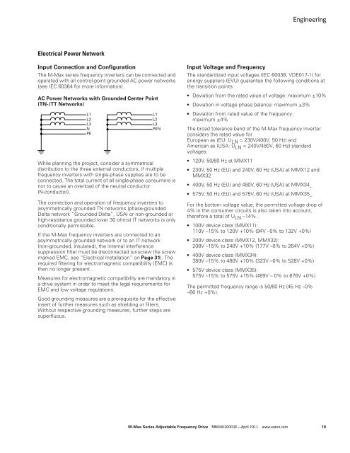
AC Power Networks with Grounded Center Point<br />
(TN-/TT Networks)<br />
L1<br />
L2<br />
L3<br />
N<br />
PE<br />
L1<br />
L2<br />
L3<br />
PEN<br />
While planning the project, consider a symmetrical<br />
distribution to the three external conductors, if multiple<br />
frequency inverters with single-phase supplies are to be<br />
connected. The total current of all single-phase consumers is<br />
not to cause an overload of the neutral conductor<br />
(N-conductor).<br />
The connection and operation of frequency inverters to<br />
asymmetrically grounded TN networks (phase-grounded<br />
Delta network “Grounded Delta”, USA) or non-grounded or<br />
high-resistance grounded (over 30 ohms) IT networks is only<br />
conditionally permissible.<br />
If the M-Max frequency inverters are connected to an<br />
asymmetrically grounded network or to an IT network<br />
(non-grounded, insulated), the internal interference<br />
suppression filter must be disconnected (unscrew the screw<br />
marked EMC, see “Electrical Installation” on Page 31). The<br />
required filtering for electromagnetic compatibility (EMC) is<br />
then no longer present.<br />
Measures for electromagnetic compatibility are mandatory in<br />
a drive system in order to meet the legal requirements for<br />
EMC and low voltage regulations.<br />
Good grounding measures are a prerequisite for the effective<br />
insert of further measures such as shielding or filters.<br />
Without respective grounding measures, further steps are<br />
superfluous.<br />
Engineering<br />
Input Voltage and <strong>Frequency</strong><br />
The standardized input voltages (IEC 60038, VDE017-1) for<br />
energy suppliers (EVU) guarantee the following conditions at<br />
the transition points:<br />
● Deviation from the rated value of voltage: maximum ±10%<br />
● Deviation in voltage phase balance: maximum ±3%<br />
● Deviation from rated value of the frequency:<br />
maximum ±4%<br />
The broad tolerance band of the M-Max frequency inverter<br />
considers the rated value for<br />
European as (EU: ULN = 230V/400V, 50 Hz) and<br />
American as (USA: ULN = 240V/480V, 60 Hz) standard<br />
voltages:<br />
● 120V, 50/60 Hz at MMX11<br />
● 230V, 50 Hz (EU) and 240V, 60 Hz (USA) at MMX12 and<br />
MMX32<br />
● 400V, 50 Hz (EU) and 480V, 60 Hz (USA) at MMX34_<br />
● 575V, 50 Hz (EU) and 575V, 60 Hz (USA) at MMX35_<br />
For the bottom voltage value, the permitted voltage drop of<br />
4% in the consumer circuits is also taken into account,<br />
therefore a total of U LN –14%.<br />
● 100V device class (MMX11):<br />
110V –15% to 120V +10% (94V –0% to 132V +0%)<br />
● 200V device class (MMX12, MMX32):<br />
208V –15% to 240V +10% (177V –0% to 264V +0%)<br />
● 400V device class (MMX34):<br />
380V –15% to 480V +10% (323V –0% to 528V +0%)<br />
● 575V device class (MMX35):<br />
575V –15% to 575V +15% (489V – 0% to 676V +0%)<br />
The permitted frequency range is 50/60 Hz (45 Hz –0%<br />
–66 Hz +0%).<br />
M-Max <strong>Series</strong> <strong>Adjustable</strong> <strong>Frequency</strong> <strong>Drive</strong> MN04020003E—April 2011 www.eaton.com 19


