

M-Maxâ„¢ Series Adjustable Frequency Drive - Eaton Corporation
M-Maxâ„¢ Series Adjustable Frequency Drive - Eaton Corporation
M-Maxâ„¢ Series Adjustable Frequency Drive - Eaton Corporation

You also want an ePaper? Increase the reach of your titles
YUMPU automatically turns print PDFs into web optimized ePapers that Google loves.
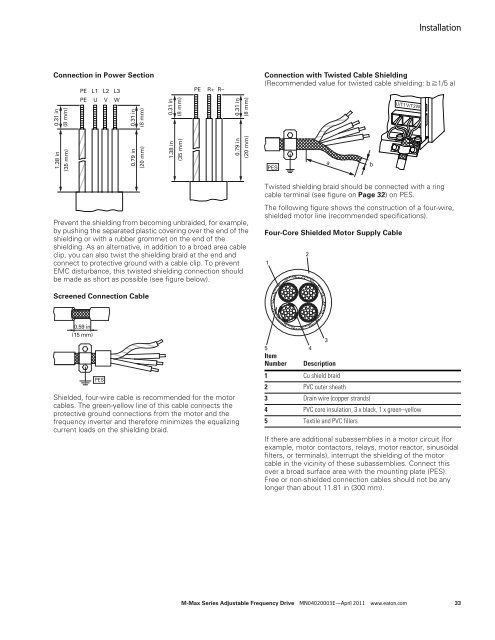
Connection in Power Section<br />
0.31 in<br />
(8 mm)<br />
1.38 in<br />
(35 mm)<br />
PE L1 L2 L3<br />
PE U V W<br />
0.31 in<br />
(8 mm)<br />
0.79 in<br />
(20 mm)<br />
Prevent the shielding from becoming unbraided, for example,<br />
by pushing the separated plastic covering over the end of the<br />
shielding or with a rubber grommet on the end of the<br />
shielding. As an alternative, in addition to a broad area cable<br />
clip, you can also twist the shielding braid at the end and<br />
connect to protective ground with a cable clip. To prevent<br />
EMC disturbance, this twisted shielding connection should<br />
be made as short as possible (see figure below).<br />
Screened Connection Cable<br />
0.59 in<br />
(15 mm)<br />
PES<br />
0.31 in<br />
(8 mm)<br />
1.38 in<br />
(35 mm)<br />
PE R+ R–<br />
Shielded, four-wire cable is recommended for the motor<br />
cables. The green-yellow line of this cable connects the<br />
protective ground connections from the motor and the<br />
frequency inverter and therefore minimizes the equalizing<br />
current loads on the shielding braid.<br />
0.31 in<br />
(8 mm)<br />
0.79 in<br />
(20 mm)<br />
Installation<br />
Connection with Twisted Cable Shielding<br />
(Recommended value for twisted cable shielding: b 1/5 a)<br />
Twisted shielding braid should be connected with a ring<br />
cable terminal (see figure on Page 32) on PES.<br />
The following figure shows the construction of a four-wire,<br />
shielded motor line (recommended specifications).<br />
Four-Core Shielded Motor Supply Cable<br />
1<br />
PES<br />
2<br />
U/T1V/T2W/T3<br />
3<br />
5<br />
4<br />
Item<br />
Number Description<br />
1 Cu shield braid<br />
2 PVC outer sheath<br />
3 Drain wire (copper strands)<br />
4 PVC core insulation, 3 x black, 1 x green–yellow<br />
5 Textile and PVC fillers<br />
If there are additional subassemblies in a motor circuit (for<br />
example, motor contactors, relays, motor reactor, sinusoidal<br />
filters, or terminals), interrupt the shielding of the motor<br />
cable in the vicinity of these subassemblies. Connect this<br />
over a broad surface area with the mounting plate (PES).<br />
Free or non-shielded connection cables should not be any<br />
longer than about 11.81 in (300 mm).<br />
M-Max <strong>Series</strong> <strong>Adjustable</strong> <strong>Frequency</strong> <strong>Drive</strong> MN04020003E—April 2011 www.eaton.com 33<br />
a<br />
b


