

M-Maxâ„¢ Series Adjustable Frequency Drive - Eaton Corporation
M-Maxâ„¢ Series Adjustable Frequency Drive - Eaton Corporation
M-Maxâ„¢ Series Adjustable Frequency Drive - Eaton Corporation

You also want an ePaper? Increase the reach of your titles
YUMPU automatically turns print PDFs into web optimized ePapers that Google loves.
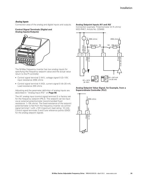
Analog Inputs<br />
Connection area of the analog and digital inputs and outputs.<br />
Control Signal Terminals (Digital and<br />
Analog Inputs/Outputs)<br />
The M-Max frequency inverter has two analog inputs for<br />
specifying the frequency setpoint value and the actual value<br />
return to the PI controller:<br />
● Control signal terminal 2 (AI1), voltage signal 0 (2)–10V,<br />
input resistance 200k ohms<br />
● Control signal terminal 4 (AI2), current signal 0 (4)–20 mA,<br />
Load resistance 200 ohms<br />
Adjusting and the parameter definition of analog inputs are<br />
described in “Analog Input (P2)” on Page 66.<br />
The AI1 analog input (control signal terminal 2) is factory set<br />
for the frequency setpoint (P6.2). The setpoint can be input<br />
via an external potentiometer (recommended fixed<br />
resistance: 1–10k ohms). The fixed resistance of the setpoint<br />
potentiometer is fed from the frequency inverter via control<br />
signal terminal 1 with +10V (maximum load rating: 10 mA).<br />
Control signal terminals 3 and 5 are reference points (GND)<br />
for the analog setpoint signals.<br />
Analog Setpoint Inputs AI1 and AI2<br />
Connection example: Potentiometer (4.7k ohms)<br />
M22-R4K7; Article No. 229490<br />
GND<br />
AI1<br />
3 1 2<br />
5 4<br />
Analog Setpoint Value Signal, for Example, from a<br />
Superordinate Controller (PLC)<br />
GND<br />
+10V Out<br />


