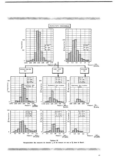
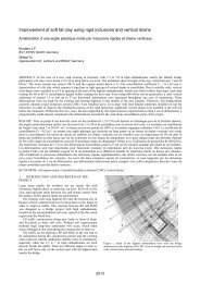
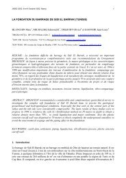
O/A//A-\\•ûoABO 10,5t et 8,5 taBomagBW200Moyen Gros Gros Moyen Fin Granu tarit e'PoudingueMarnesbleuesEboulisMarnocalcaireFlyschMatériauFig. 3 - Influence du type de compacteur sur le tassementT pour divers types de matériaux.passes (4 ou 5 dans notre cas). Nous avonségalement constaté, qu'à teneur en eau élevée dela fraction 0/12,5 mm, mais inférieur à la limite deplasticité, ce phénomène était pratiquement inexistant.On peut, dans ce cas, supposer :— qu'il est plus difficile de mettre en mouvement leséléments solides en raison de l'adhérence plus forteexistant entre grains,— qu'une partie de l'énergie vibratoire est amortiedans la phase fluide.Nous avons testé, durant le chantier, sur diversmatériaux (fins, rocheux) deux types de compacteurde principe différent. L'analyse des tassements T etdes densités T anous permet de penser que :— pour le sol rocheux à fort pourcentage de blocs,seuls les vibrants lourds conviennent ;— pour les sols fins, mis en couches épaisses, lecompacteur ABG, surpuissant, peut avantageusementêtre remplacé par un engin type BW 200.Ces éléments sont mis en place avec un nombreréduit de passes alors que les gros éléments nesont pratiquement pas intéressés, même si on multipliele nombre de passes.Pour les ABG, tous les éléments sont intéressés,mais, malgré l'énergie supérieure, il est nécessaired'augmenter le nombre de passes pour parfaire lamise en place des gros éléments.c) Des densités en place ont été exécutées dansles éléments fins du flysch, avec correction del'optimum proctor normal (O.P.N.) en fonction dupourcentage d'éléments supérieurs à 12,5 mm (densitésréalisées à — 20 cm (40 '%) et à — 40 cm(60 %) de la surface) (fig. U et tableau IX).Les résultats obtenus sont similaires pour le BW 200et l'ABG 10,5 t, confirmant l'hypothèse énoncée auparagraphe : « Comparaisons des énergies développéespar le compacteur BW 200 et les compacteursABG », à savoir l'égalité des actions sur les élémentsfins (fig. 5).d) Lorsque le matériau est « fragile » (flysch, marnocalcaire)l'énergie développée par les compacteursABG, fragmente le matériau dans la couche et surtouten surface, modifiant la granularité et agissantsur les tassements L. Cette modification se produisantà chaque passe, il est parfois difficile d'obtenirune asymptote de tassement.Ce phénomène, apparu avec l'emploi des vibrantslourds, type ABG, n'avait pas été observé pendantla réalisation du remblai expérimental. En effet, àl'époque, nous n'avions pas à notre disposition cetype de compacteur. Nous avions constaté, en coursde chantier, que cette fragmentation des matériaux,importante en surface, entraînait un foisonnement etune ségrégation de la couche superficielle, phénomènese produisant en fin de compactage et s'accentuantavec le nombre de passes. Il semblerait queles éléments en surface, constamment en mouvement,ne trouvent aucune possibilité d'arrangementoptimal. Seul un engin statique peut fermer la surfacede la couche. Lorsque ce phénomène se produitil est préférable de limiter le nombre de2 - Influence du répandeur(fig. 6 et tableaux II à VII)Examinons sur les tableaux IV, V, VII, les sous-famillessuivantes :— Marno-calcaire : BW 200 - TD 25 (International)BW 200 - Michlgan— Calcaire : BW 200 - D8 (Caterpillar)BW 200 - D6 (Caterpillar)— Eboulis : ABG 10,5 t - D8 (Caterpillar)ABG 10,5 t - D6 (Caterpillar)Pour un type de matériau et de compacteur donnés,les tassements T diminuent lorsque la puissance durépandeur augmente et cela, à granularité pratiquementconstante.Dans les autres cas (tableaux II, III, VI)— Poudingue : BW 200 - D6 (Caterpillar)BW 200 - D8 (Caterpillar)— Marnes bleues : ABG 10,5 t - D6 (Caterpillar)ABG 10,5 t - Michigan— Flysch : BW 200 - D6 (Caterpillar)BW 200 - D4 (Caterpillar)La comparaison est rendue difficile par la différencede granularité. Cependant, cette notion semble1.00.90,820 40 60 80 tOOcnEpaisseur d unecoucheFig. 4 - Evolution du rapport à l'intérieur d'une couchede remblai."^d O P N46
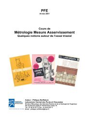
RESULTATS D ENSEMBLE200200N = 822N = 829100X = 1,00P"= 0,0 4100* = 0,7 9(T= 0/3-4 J0,650 0,900 0,950 1,000 1/150 1,100 1,150I'dR app o rtÜ'dO.RNJ0,3 0,6 0,9 1,2WV.Rapportwr.o.p.N.BOMAG BW 2000 6ABG10,St.D 6RICHIERD6N=401X= 0,990"= 0,03200N =236X = 1,01
- Page 1: 1AUTOROUTE DE MENTON
- Page 4 and 5: En couvertureL'arrivée en Francevu
- Page 7 and 8: J. TANZIDirecteur départemental de
- Page 9 and 10: —SAINTE AGNES MENTON+long.de part
- Page 11 and 12: XPour l'exécution des déblais, il
- Page 13 and 14: Nous avons été alors amenés à d
- Page 15 and 16: QUEL EST LE BILAN DE L'OPÉRATION ?
- Page 18 and 19: Vue aérienne d'une partie de l'aut
- Page 21 and 22: Etage Faciès CaractèreIQuaternair
- Page 23 and 24: Fig. 5 - Crétacésupérieur. Marno
- Page 26 and 27: Fig. 8 - Miocène : poudingue de Ro
- Page 28 and 29: Tous ces mouvements se sont produit
- Page 30 and 31: Elle fut systématique pour les fon
- Page 32: Fig. 15 - Prétranchée de Ruffa.Fl
- Page 35 and 36: O. DELAHAYEIngénieur des Arts et m
- Page 37 and 38: Poudingue u» 8AB G 10,5t t 6Marnos
- Page 39 and 40: Analyse des résultats des contrôl
- Page 41 and 42: EBOULISRESULTATS D ENSEMBLE100100V.
- Page 43 and 44: FLYSCHRESULTATS D'ENSEMBLE100100 V.
- Page 45: T A B L E A UVIIITableau récapitul
- Page 49 and 50: Pour les autres types de matériaux
- Page 51 and 52: S. A M ARAssistantSection des fonda
- Page 53 and 54: Fig. 3 - Remblai de Quiaus le 4 jan
- Page 55 and 56: SN = P' COSaST = ~P' Sina + Eoù E
- Page 57 and 58: Tableau récapitulatif. Résultats
- Page 59 and 60: Eaux de ruissellementdu bassin vers
- Page 61 and 62: A. VIIMCENTELLiIngénieur des T.P.E
- Page 63 and 64: le nombre, ne peuvent donner qu'un
- Page 65 and 66: TABLEAU IV (suite)Diamètre destrou
- Page 67 and 68: corrects des trous de forage. Même
- Page 69 and 70: Première partie.D E T A I L ©Deux
- Page 71 and 72: Il convient ici de définir les ter
- Page 73 and 74: M. MARECJ. LEGRANDG. CHAMPETIER DE
- Page 75 and 76: du niveau du toit du substratum de
- Page 77 and 78: Pied du glissement sud et amorce du
- Page 79 and 80: 1Hied du glissement nord et amorce
- Page 81 and 82: ass» oujurTTSubstratummarnesmiocè
- Page 83 and 84: tenu de toutes les variables en pr
- Page 85 and 86: x Sondage électrique• Sondage di
- Page 87 and 88: de véritables couches de marnes al
- Page 89 and 90: il'hypothèse de la présence d'une
- Page 91 and 92: ChausséeFig. 14 - Croquis montrant
- Page 93 and 94: Mur en terre arméesu p e'ri eu r_M
- Page 97 and 98:
Les essais d'identification Y = 2 t
- Page 100 and 101:
Le mur du Peyronnet (hauteur : 23 m
- Page 102 and 103:
En définitive, la synthèse de ces
- Page 104 and 105:
On se trouve donc amené à augment
- Page 106 and 107:
La longueur et l'encastrement des m
- Page 108 and 109:
D'autre part, lorsqu'il s'agit d'ap
- Page 110 and 111:
Caractéristiques de chaquemurLa Gi
- Page 112 and 113:
PeyronnetMurinférieurLongueur à l
- Page 114:
Vigna IIMurinférieurLongueur : 177
- Page 117 and 118:
S. AMARJ.-P.MENEROUDG. PILOTFondati
- Page 119 and 120:
p ¡Fig. 1 - Système expérimental
- Page 121 and 122:
Fig. 4 - Viaduc du Careï, rive dro
- Page 123 and 124:
iNICEFig. 8 - Viaduc du Pala. Profi
- Page 125 and 126:
cisaillement (c' = 0, ?' = 24°) so
- Page 127 and 128:
terrassements de la piste d'accès.
- Page 129 and 130:
Fig. 19 - Viaduc du Baousset, site
- Page 131 and 132:
Fig. 23 - Viaduc du Fossan, culée
- Page 133 and 134:
F. BAGUELINB. GAUDINIngénieur E.I.
- Page 135 and 136:
MINISTERE DE L'EQUIPEMENT ET DU LOG
- Page 137:
Mrs
- Page 140 and 141:
du puits, ces marnes sont très cer
- Page 142 and 143:
fut adopté pour le flysch (grès +
- Page 144 and 145:
Fig. 9 - Vue d'ensemble de la fonda
- Page 146 and 147:
0 10 20 30 «0 50 bars 0 10 20 30 4
- Page 148 and 149:
pieu, et la concavité serait alors
- Page 150 and 151:
avec les cadences d'exécutionréce
- Page 152 and 153:
Lesperformances des bétons et des
- Page 154 and 155:
Centrales A B A • B . cR c 90 jou
- Page 156 and 157:
B 300AMurs et ouvrages hydrauliques
- Page 158 and 159:
Influence du filler et de l'équiva
- Page 160 and 161:
Problèmes généraux de la surveil
- Page 162 and 163:
Un ingénieurchefde subdivisionW\\U
- Page 165 and 166:
iENTREPRISE : &..X..M.. OuvrageDate
- Page 167 and 168:
Fig. 9 - Sur une plate-forme de 50
- Page 170 and 171:
Tunnel de la Couplère.
- Page 172 and 173:
Le tunnel du Peyronnet. Le tube sud
- Page 174 and 175:
sud. Le piédroit central, qui tass
- Page 176 and 177:
cières des décisions prises sur l
- Page 178 and 179:
Le tunnel traverse des marno-calcai
- Page 180 and 181:
Tassement des piédroitset mesure d
- Page 182 and 183:
a) Cintre n'2 PM: 70,05Cintres n os
- Page 184 and 185:
80G5G6GA//—/G2G5G1C/ttGi, /AS//>-
- Page 186 and 187:
Par ailleurs, les mesurés topograp
- Page 188 and 189:
Déroulement du chantierPercement d
- Page 190 and 191:
SolutionsenvisagéesUne galerie éb
- Page 192 and 193:
2. Aménagement d'une piste d'accè
- Page 194 and 195:
A cet effet, le choix du coulis d'i
- Page 196 and 197:
Montant définitif de la dépenseBi
- Page 198 and 199:
Viaduc du Pescalre et tunnel du San
- Page 200 and 201:
Restitution de plan par photogramm
- Page 202 and 203:
déterminations de chaque point, ce
- Page 204 and 205:
déterminées périodiquement par t
- Page 206 and 207:
ZusammenfassungDie Sondernummer «