Challenges and Opportunities for Innovation in the Public Works ...
Challenges and Opportunities for Innovation in the Public Works ...
Challenges and Opportunities for Innovation in the Public Works ...
You also want an ePaper? Increase the reach of your titles
YUMPU automatically turns print PDFs into web optimized ePapers that Google loves.
correct. Conduit is not usually modeled s<strong>in</strong>ce it is normally run<br />
to suit exist<strong>in</strong>g field conditions.<br />
A compromise needs to be made between <strong>the</strong> <strong>in</strong>itial cost of <strong>the</strong><br />
detailed 3-D model <strong>and</strong> <strong>the</strong> downstream sav<strong>in</strong>gs of hav<strong>in</strong>g this<br />
<strong>in</strong><strong>for</strong>mation available <strong>for</strong> estimat<strong>in</strong>g, purchas<strong>in</strong>g, <strong>and</strong> project<br />
control. This does not preclude specific areas of <strong>the</strong> design be<strong>in</strong>g<br />
modeled <strong>in</strong> a high level of detail <strong>for</strong> study purposes.<br />
APPLICATIONS<br />
Duct Removal Project<br />
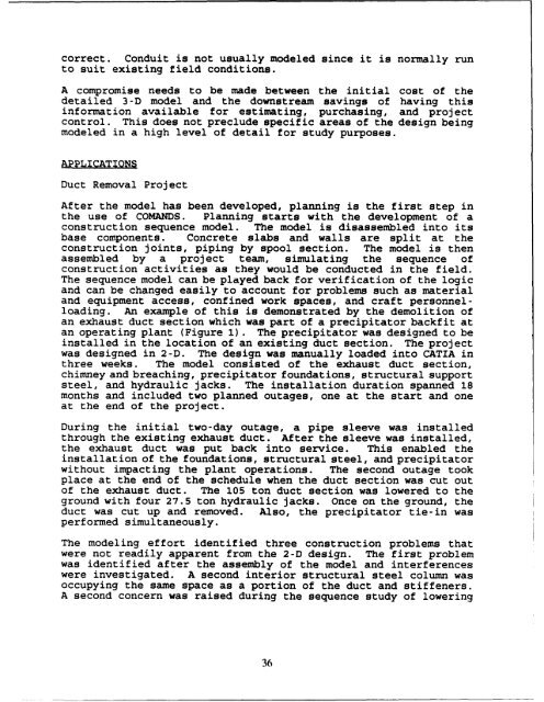
After <strong>the</strong> model has been developed, plann<strong>in</strong>g is <strong>the</strong> first step <strong>in</strong><br />
<strong>the</strong> use of COMANDS. Plann<strong>in</strong>g starts with <strong>the</strong> development of a<br />
construction sequence model. The model is disassembled <strong>in</strong>to its<br />
base components. Concrete slabs <strong>and</strong> walls are split at <strong>the</strong><br />
construction jo<strong>in</strong>ts, pip<strong>in</strong>g by spool section. The model is <strong>the</strong>n<br />
assembled by a project team, simulat<strong>in</strong>g <strong>the</strong> sequence of<br />
construction activities as <strong>the</strong>y would be conducted <strong>in</strong> <strong>the</strong> field.<br />
The sequence model can be played back <strong>for</strong> verification of <strong>the</strong> logic<br />
<strong>and</strong> can be changed easily to account <strong>for</strong> problems such as material<br />
<strong>and</strong> equipment access, conf<strong>in</strong>ed work spaces, <strong>and</strong> craft personnelload<strong>in</strong>g.<br />
An example of this is demonstrated by <strong>the</strong> demolition of<br />
an exhaust duct section which was part of a precipitator backfit at<br />
an operat<strong>in</strong>g plant (Figure 1). The precipitator was designed to be<br />
<strong>in</strong>stalled <strong>in</strong> <strong>the</strong> location of an exist<strong>in</strong>g duct section. The project<br />
was designed <strong>in</strong> 2-D. The design was manually loaded <strong>in</strong>to CATIA <strong>in</strong><br />
three weeks. The model consisted of <strong>the</strong> exhaust duct section,<br />
chimney <strong>and</strong> breach<strong>in</strong>g, precipitator foundations, structural support<br />
steel, <strong>and</strong> hydraulic jacks. The <strong>in</strong>stallation duration spanned 18<br />
months <strong>and</strong> <strong>in</strong>cluded two planned outages, one at <strong>the</strong> start <strong>and</strong> one<br />
at <strong>the</strong> end of <strong>the</strong> project.<br />
Dur<strong>in</strong>g <strong>the</strong> <strong>in</strong>itial two-day outage, a pipe sleeve was <strong>in</strong>stalled<br />
through <strong>the</strong> exist<strong>in</strong>g exhaust duct. After <strong>the</strong> sleeve was <strong>in</strong>stalled,<br />
<strong>the</strong> exhaust duct was put back <strong>in</strong>to service. This enabled <strong>the</strong><br />
<strong>in</strong>stallation of <strong>the</strong> foundations, structural steel, <strong>and</strong> precipitator<br />
without impact<strong>in</strong>g <strong>the</strong> plant operations. The second outage took<br />
place at <strong>the</strong> end of <strong>the</strong> schedule when <strong>the</strong> duct section was cut out<br />
of <strong>the</strong> exhaust duct. The 105 ton duct section was lowered to <strong>the</strong><br />
ground with four 27.5 ton hydraulic jacks. Once on <strong>the</strong> ground, <strong>the</strong><br />
duct was cut up <strong>and</strong> removed. Also, <strong>the</strong> precipitator tie-<strong>in</strong> was<br />
per<strong>for</strong>med simultaneously.<br />
The model<strong>in</strong>g ef<strong>for</strong>t identified three construction problems that<br />
were not readily apparent from <strong>the</strong> 2-D design. The first problem<br />
was identified after <strong>the</strong> assembly of <strong>the</strong> model <strong>and</strong> <strong>in</strong>terferences<br />
were <strong>in</strong>vestigated. A second <strong>in</strong>terior structural steel column was<br />
occupy<strong>in</strong>g <strong>the</strong> same space as a portion of <strong>the</strong> duct <strong>and</strong> stiffeners.<br />
A second concern was raised dur<strong>in</strong>g <strong>the</strong> sequence study of lower<strong>in</strong>g<br />
36


