EPOS2 Application Notes Collection - Maxon Motor
EPOS2 Application Notes Collection - Maxon Motor
EPOS2 Application Notes Collection - Maxon Motor

Create successful ePaper yourself
Turn your PDF publications into a flip-book with our unique Google optimized e-Paper software.
CANopen Basic Information<br />
Configuration<br />
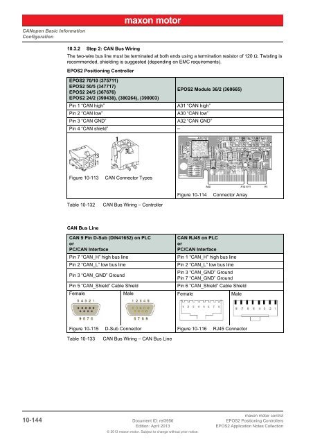
10.3.2 Step 2: CAN Bus Wiring<br />
The two-wire bus line must be terminated at both ends using a termination resistor of 120 Ω. Twisting is<br />
recommended, shielding is suggested (depending on EMC requirements).<br />
<strong>EPOS2</strong> Positioning Controller<br />
<strong>EPOS2</strong> 70/10 (375711)<br />
<strong>EPOS2</strong> 50/5 (347717)<br />
<strong>EPOS2</strong> 24/5 (367676)<br />
<strong>EPOS2</strong> 24/2 (390438), (380264), (390003)<br />
<strong>EPOS2</strong> Module 36/2 (360665)<br />
Pin 1 “CAN high”<br />
A31 “CAN high”<br />
Pin 2 “CAN low”<br />
A30 “CAN low”<br />
Pin 3 “CAN GND”<br />
A32 “CAN GND”<br />
Pin 4 “CAN shield” –<br />
Figure 10-113<br />
CAN Connector Types<br />
Figure 10-114<br />
Connector Array<br />
Table 10-132<br />
CAN Bus Wiring – Controller<br />
CAN Bus Line<br />
CAN 9 Pin D-Sub (DIN41652) on PLC<br />
or<br />
PC/CAN Interface<br />
Pin 7 “CAN_H” high bus line<br />
Pin 2 “CAN_L” low bus line<br />
CAN RJ45 on PLC<br />
or<br />
PC/CAN Interface<br />
Pin 1 “CAN_H” high bus line<br />
Pin 2 “CAN_L” low bus line<br />
Pin 3 “CAN_GND” Ground<br />
Pin 3 “CAN_GND” Ground<br />
Pin 7 “CAN_GND” Ground<br />
Pin 5 “CAN_Shield” Cable Shield<br />
Pin 6 “CAN_Shield” Cable Shield<br />
Female Male Female Male<br />
Figure 10-115 D-Sub Connector Figure 10-116 RJ45 Connector<br />
Table 10-133<br />
CAN Bus Wiring – CAN Bus Line<br />
maxon motor control<br />
10-144 Document ID: rel3956 <strong>EPOS2</strong> Positioning Controllers<br />
Edition: April 2013<br />
<strong>EPOS2</strong> <strong>Application</strong> <strong>Notes</strong> <strong>Collection</strong><br />
© 2013 maxon motor. Subject to change without prior notice.