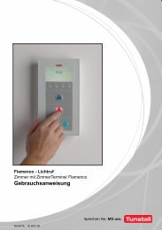
Flamenco Technical Manual Revision 6.0 - Tunstall.de
Flamenco Technical Manual Revision 6.0 - Tunstall.de
Flamenco Technical Manual Revision 6.0 - Tunstall.de

You also want an ePaper? Increase the reach of your titles
YUMPU automatically turns print PDFs into web optimized ePapers that Google loves.
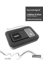
Installationsanleitung D Installation Instructions GB<br />
Pneumatischer Ruftaster, Best.‐Nr. 70 0106 00<br />
Taster zur Rufauslösung durch pneumatische Betätigung. Das integrierte Beruhigungslicht<br />
leuchtet auf, sobald ein Ruf ausgelöst wird. Vorzugsweise hergestellt für <strong>de</strong>n Wan<strong>de</strong>inbau.<br />
Pneumatischer Ruftaster/WC, Best.‐Nr. 70 0106 01<br />
Wie Bestell‐Nr. 70 0106 00, jedoch für WC‐Ruf und WC‐Notruf.<br />
Hinweis! Die vollständige Installation <strong>de</strong>s Systems ist im technischen Handbuch<br />
beschrieben.<br />
Achtung! Die Leiterplatte ist mit elektrostatisch gefähr<strong>de</strong>ten Bauteilen bestückt.<br />
Vermei<strong>de</strong>n Sie <strong>de</strong>shalb eine direkte Berührung.<br />
Pneumatic call switch, or<strong>de</strong>r no. 70 0106 00<br />
One call button with pneumatic function for call activation, complete with integrate reassurance<br />
lamp. Suitable for wall mounting.<br />
Pneumatic call switch/WC, or<strong>de</strong>r no. 70 0106 01<br />
As 70 0106 00, but for WC rooms.<br />
Note! The complete installation of the system is <strong>de</strong>scribed in the technical<br />
manual.<br />
Attention! The printed circuit board inclu<strong>de</strong>s electrostatic sensitive components.<br />
Avoid touching.<br />
<strong>Tunstall</strong> GmbH, Orkotten 66, D-48291 Telgte, www.tunstall.<strong>de</strong><br />
Montage<br />
1* Einbaudose<br />
2 Klemmkralle<br />
3 Montagerahmen<br />
4* Anschlussklemme (70 0807 00)<br />
* ist nicht im Lieferumfang enthalten.<br />
5 Leiterplatte (vormontiert)<br />
6 Tastergehäuse<br />
7 Luftschlauch<br />
8 Gummiball<br />
1. Angeschlossene Anschlussklemme 4 durch <strong>de</strong>n Montagerahmen 3 ziehen.<br />
2. - Einbaudose Mauerwerk: Den Montagerahmen 3 mit <strong>de</strong>r Klemmkralle 2 an <strong>de</strong>r<br />
Einbaudose 1 befestigen (Mittenversatz!).<br />
- Einbaudose Hohlwand: Montagerahmen 3 an <strong>de</strong>n Schraubpunkten <strong>de</strong>r Einbaudose 1<br />
verschrauben (Mittenversatz!)<br />
3. Anschlussklemme 4 in die eingebaute Buchse <strong>de</strong>r Leiterplatte 5 stecken.<br />
4. Tastergehäuse 6 über <strong>de</strong>n Montagerahmen 3 drücken und einrasten lassen.<br />
5. Falls erfor<strong>de</strong>rlich: Den Luftschlauch 7 auf die gewünschte Länge kürzen und <strong>de</strong>n<br />
Gummiball 8 wie<strong>de</strong>r aufstecken.<br />
Anschluss Zimmerbus (RAN) ohne Sprechen<br />
vom RAN-Teilnehmer<br />
B (lack) = 0V schwarz<br />
Y (ellow) = RAN gelb<br />
R (ed) = +24 V rot<br />
Kanalcodierung<br />
Die Ruftaster können zur Bildung von Funktionseinheiten verschie<strong>de</strong>nen Kanälen<br />
zugeordnet wer<strong>de</strong>n.<br />
Die Kanalnummern wer<strong>de</strong>n an einer markierten Stelle auf <strong>de</strong>r Leiterplatte (P1, P2, P3)<br />
durch Trennen (Messer) bzw. Verbin<strong>de</strong>n (Löten) eingestellt.<br />
Werkseitig ist immer die Kanalnummer 0 eingestellt.<br />
Die einzustellen<strong>de</strong> Kanalnummer entnehmen Sie <strong>de</strong>m entsprechen<strong>de</strong>n Installationsplan.<br />
Beispiel Kanal 6:<br />
P2 und P3 trennen<br />
= Lötpunkt<br />
Zum Wie<strong>de</strong>rverbin<strong>de</strong>n<br />
= 6<br />
getrennter Leitungen<br />
= werkseitig verbun<strong>de</strong>n<br />
= getrennt<br />
Demontage<br />
1. Schraubendreher an <strong>de</strong>r Rastnase ansetzen und Tastergehäuse abhebeln.<br />
2. Anschlussklemme 4 abziehen.<br />
3. Schraube am Montagerahmen 3 lösen.<br />
B<br />
Y<br />
R<br />
Mounting<br />
1* Back box<br />
2 Fixing clamp<br />
3 Mounting frame<br />
4* Connector (70 0807 00)<br />
* not inclu<strong>de</strong>d with product <strong>de</strong>livery.<br />
5 Printed circuit board PCB (pre‐mounted)<br />
6 Switch housing<br />
7 Air tube<br />
8 Rubber ball<br />
1. Pull the cable‐connected connector 4 through the mounting frame 3.<br />
2. - Back box for solid walls: Use the fixing clamp 2 to fix the mounting frame 3 to the back<br />
box 1 (centre offset!).<br />
- Back box for partition walls: Screw the mounting frame 3 to the screw points of the<br />
back box 1 (centre offset!).<br />
3. Plug the connector 4 into the socket on the PCB 5.<br />
4. Push and lock in the switch housing 6 onto the mounting frame 3.<br />
5. If necessary, shorten the air tube to length and refit the rubber ball.<br />
Connection of room bus (RAN) without speech<br />
from RAN user<br />
B (lack) = 0V<br />
Y (ellow) = RAN<br />
R (ed) = +24 V<br />
Channel coding<br />
If functional units are requested, the switches have to be assigned to different channels.<br />
The channel number is configured at the position marked on the PCB (P1, P2, P3) by<br />
breaking the links (cutter) or reconnecting (sol<strong>de</strong>r). The product is pre‐set on channel 0.<br />
For the channel number to be set please refer to the installation plan.<br />
Example channel number 6:<br />
Break links P2 and P3<br />
= 6<br />
= pre-set link<br />
= broken link<br />
B<br />
Y<br />
R<br />
= Sol<strong>de</strong>r point<br />
to reconnect a broken link<br />
Dismantling<br />
1. Using a screw driver, prize the switch cover from above away from the mounting frame.<br />
2. Remove the connector 4.<br />
3. Unscrew the mounting frame 3.<br />
3<br />
1<br />
2<br />
4<br />
5<br />
7<br />
8<br />
6<br />
Einbaudose Hohlwand (17 5100 00),<br />
Mittenversatz:<br />
Back box partition wall (17 5100 00),<br />
Centre offset:<br />
1<br />
3<br />
P1 P2<br />
P3<br />
Kanalnummer<br />
Channel number<br />
= 0<br />
= 1<br />
= 2<br />
= 3<br />
= 4<br />
= 5<br />
= 6<br />
= 7<br />
70 0106 00<br />
Pneumatischer Ruftaster<br />
Pneumatic call switch<br />
70 0106 01<br />
Pneumatischer Ruftaster/WC<br />
Pneumatic call switch/WC<br />
00 8800 22, 09/11 (Rev. 3.1)<br />
Page 100