Flamenco Technical Manual Revision 6.0 - Tunstall.de
Flamenco Technical Manual Revision 6.0 - Tunstall.de
Flamenco Technical Manual Revision 6.0 - Tunstall.de

You also want an ePaper? Increase the reach of your titles
YUMPU automatically turns print PDFs into web optimized ePapers that Google loves.
Power supply unit UPS 60, Or<strong>de</strong>r No. 77 3400 10<br />
2.3 Control terminal clamps x + y<br />
The control terminal clamps "x" and "y" are used to prepare the unit for the uninterrupted power supply<br />
(UPS mo<strong>de</strong>).<br />
2.3.1 Preparing the UPS function by placing a bridge contact between "x" and "y"<br />
• Connect the control terminal clamps "x" and "y" using the enclosed bridging contact or via a<br />
potential-free 'make contact'. The current for the bridging contact is approx. 1 mA..<br />
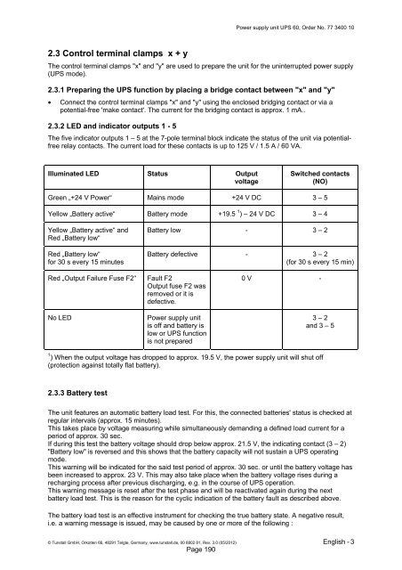
2.3.2 LED and indicator outputs 1 - 5<br />
The five indicator outputs 1 – 5 at the 7-pole terminal block indicate the status of the unit via potentialfree<br />
relay contacts. The current load for these contacts is up to 125 V / 1.5 A / 60 VA.<br />
Illuminated LED Status Output<br />
voltage<br />
Switched contacts<br />
(NO)<br />
Green „+24 V Power“ Mains mo<strong>de</strong> +24 V DC 3 – 5<br />
Yellow „Battery active“ Battery mo<strong>de</strong> +19.5 1 ) – 24 V DC 3 – 4<br />
Yellow „Battery active“ and<br />
Red „Battery low“<br />
Red „Battery low“<br />
for 30 s every 15 minutes<br />
Battery low - 3 – 2<br />
Battery <strong>de</strong>fective - 3 – 2<br />
(for 30 s every 15 min)<br />
Red „Output Failure Fuse F2“<br />
No LED<br />
Fault F2<br />
Output fuse F2 was<br />
removed or it is<br />
<strong>de</strong>fective.<br />
Power supply unit<br />
is off and battery is<br />
low or UPS function<br />
is not prepared<br />
0 V -<br />
3 – 2<br />
and 3 – 5<br />
1 ) When the output voltage has dropped to approx. 19.5 V, the power supply unit will shut off<br />
(protection against totally flat battery).<br />
2.3.3 Battery test<br />
The unit features an automatic battery load test. For this, the connected batteries' status is checked at<br />
regular intervals (approx. 15 minutes).<br />
This takes place by voltage measuring while simultaneously <strong>de</strong>manding a <strong>de</strong>fined load current for a<br />
period of approx. 30 sec.<br />
If during this test the battery voltage should drop below approx. 21.5 V, the indicating contact (3 – 2)<br />
"Battery low" is reversed and this shows that the battery capacity will not sustain a UPS operating<br />
mo<strong>de</strong>.<br />
This warning will be indicated for the said test period of approx. 30 sec. or until the battery voltage has<br />
been increased to approx. 23 V. This may also take place when the battery voltage rises during a<br />
recharging process after previous discharging, e.g. in the course of UPS operation.<br />
This warning message is reset after the test phase and will be reactivated again during the next<br />
battery load test. This is the reason for the cyclic indication of the battery fault as <strong>de</strong>scribed above.<br />
The battery load test is an effective instrument for checking the true battery state. A negative result,<br />
i.e. a warning message is issued, may be caused by one or more of the following :<br />
© <strong>Tunstall</strong> GmbH, Orkotten 66, 48291 Telgte, Germany, www.tunstall.<strong>de</strong>, 00 8802 81, Rev. 3.0 (05/2012) English - 3<br />
Page 190