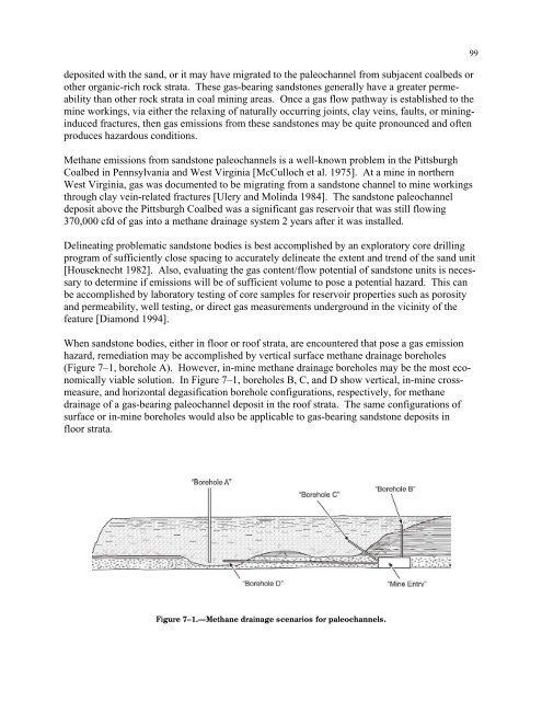
deposited with the sand, or it may have migrated to the paleochannel from subjacent coalbeds orother organic-rich rock strata. These gas-bear<strong>in</strong>g sandstones generally have a greater permeabilitythan other rock strata <strong>in</strong> coal m<strong>in</strong><strong>in</strong>g areas. Once a gas flow pathway is established to them<strong>in</strong>e work<strong>in</strong>gs, via either the relax<strong>in</strong>g of naturally occurr<strong>in</strong>g jo<strong>in</strong>ts, clay ve<strong>in</strong>s, faults, or m<strong>in</strong><strong>in</strong>g<strong>in</strong>ducedfractures, then gas emissions from these sandstones may be quite pronounced and oftenproduces hazardous conditions.<strong>Methane</strong> emissions from sandstone paleochannels is a well-known problem <strong>in</strong> the PittsburghCoalbed <strong>in</strong> Pennsylvania and West Virg<strong>in</strong>ia [McCulloch et al. 1975]. At a m<strong>in</strong>e <strong>in</strong> northernWest Virg<strong>in</strong>ia, gas was documented to be migrat<strong>in</strong>g from a sandstone channel to m<strong>in</strong>e work<strong>in</strong>gsthrough clay ve<strong>in</strong>-related fractures [Ulery and Mol<strong>in</strong>da 1984]. The sandstone paleochanneldeposit above the Pittsburgh Coalbed was a significant gas reservoir that was still flow<strong>in</strong>g370,000 cfd of gas <strong>in</strong>to a methane dra<strong>in</strong>age system 2 years after it was <strong>in</strong>stalled.Del<strong>in</strong>eat<strong>in</strong>g problematic sandstone bodies is best accomplished by an exploratory core drill<strong>in</strong>gprogram of sufficiently close spac<strong>in</strong>g to accurately del<strong>in</strong>eate the extent and trend of the sand unit[Houseknecht 1982]. Also, evaluat<strong>in</strong>g the gas content/flow potential of sandstone units is necessaryto determ<strong>in</strong>e if emissions will be of sufficient volume to pose a potential hazard. This canbe accomplished by laboratory test<strong>in</strong>g of core samples <strong>for</strong> reservoir properties such as porosityand permeability, well test<strong>in</strong>g, or direct gas measurements underground <strong>in</strong> the vic<strong>in</strong>ity of thefeature [Diamond 1994].When sandstone bodies, either <strong>in</strong> floor or roof strata, are encountered that pose a gas emissionhazard, remediation may be accomplished by vertical surface methane dra<strong>in</strong>age boreholes(Figure 7–1, borehole A). However, <strong>in</strong>-m<strong>in</strong>e methane dra<strong>in</strong>age boreholes may be the most economicallyviable solution. In Figure 7–1, boreholes B, C, and D show vertical, <strong>in</strong>-m<strong>in</strong>e crossmeasure,and horizontal degasification borehole configurations, respectively, <strong>for</strong> methanedra<strong>in</strong>age of a gas-bear<strong>in</strong>g paleochannel deposit <strong>in</strong> the roof strata. The same configurations ofsurface or <strong>in</strong>-m<strong>in</strong>e boreholes would also be applicable to gas-bear<strong>in</strong>g sandstone deposits <strong>in</strong>floor strata.99Figure 7–1.—<strong>Methane</strong> dra<strong>in</strong>age scenarios <strong>for</strong> paleochannels.
100Vertical methane dra<strong>in</strong>age boreholes drilled from the surface usually require both dewater<strong>in</strong>g andhydraulic fractur<strong>in</strong>g <strong>for</strong> maximum effectiveness. Horizontal, cross-measure, or vertical undergrounddegasification boreholes may also need to remove water to effectively produce gas.These methane dra<strong>in</strong>age systems are fully expla<strong>in</strong>ed and referenced by Diamond [1994].Gas-bear<strong>in</strong>g paleochannel deposits oradjacent coalbeds may require surface orcross-measure methane dra<strong>in</strong>age boreholes.Coalbeds and other adjacent gas source beds. Historical m<strong>in</strong><strong>in</strong>g experience and research haveshown that coalbeds adjacent to the m<strong>in</strong>ed seam can contribute significant quantities of methanegas <strong>in</strong>to active work<strong>in</strong>gs [F<strong>in</strong>f<strong>in</strong>ger and Cervik 1979; Ayruni 1984; Diamond et al. 1992].Degasification of these coalbeds may be accomplished through vertical or directional boreholesdrilled from the surface. Occasionally, <strong>in</strong>-m<strong>in</strong>e vertical, cross-measure, or directional boreholesare used to reduce potentially explosive accumulations of gas [F<strong>in</strong>f<strong>in</strong>ger and Cervik 1979;Ayruni 1984; Diamond 1994].In addition to nearby coalbeds, other adjacent strata may also be significant gas reservoirs andcontribute unexpected emissions <strong>in</strong>to m<strong>in</strong>e work<strong>in</strong>gs. Shales and siltstones rich <strong>in</strong> organic matteroften conta<strong>in</strong> significant quantities of methane gas [Darton 1915; Johnson and Flores 1998].Although these <strong>for</strong>mations may have a large gas storage capacity, permeability is usually verylow. Thus, these rocks may not release gas until m<strong>in</strong><strong>in</strong>g-<strong>in</strong>duced fractures <strong>in</strong>crease their permeabilityand provide a pathway <strong>for</strong> gas migration to the m<strong>in</strong>e work<strong>in</strong>gs. In study<strong>in</strong>g the gas contentof U.K. coalbeds, Creedy [1988] concluded that although the gas contents and porosities ofthese rocks are low, a well-developed jo<strong>in</strong>t or fracture system could facilitate gas release fromthese strata. There<strong>for</strong>e, it may be assumed that if certa<strong>in</strong> organic-rich rocks adjacent to m<strong>in</strong>edcoalbeds have sufficient gas content, migration via jo<strong>in</strong>ts or fractures <strong>in</strong>to the work<strong>in</strong>gs couldgenerate hazardous explosive conditions. <strong>Methane</strong> dra<strong>in</strong>age methods similar to those discussedpreviously <strong>for</strong> adjacent coalbeds are usually appropriate <strong>for</strong> adjacent noncoal gas-bear<strong>in</strong>g strataas well.Large- and small-scale structural fault<strong>in</strong>g. For this discussion, large-scale faults are looselydef<strong>in</strong>ed as hav<strong>in</strong>g tectonically activated and structurally mappable features, with lengths greaterthan 500 m (1,640 ft) and vertical movement of at least 10–20 m (33–66 ft). Small-scale faultsare dist<strong>in</strong>guished from large-scale faults by their limited extent both horizontally and vertically.Faults may have a profound effect on gas emissions <strong>in</strong>to m<strong>in</strong>e work<strong>in</strong>gs and may also be associatedwith outbursts and blowers. Usually, the presence of large-scale fault<strong>in</strong>g is known fromregional geologic mapp<strong>in</strong>g and/or exploration boreholes. In certa<strong>in</strong> cases, these large faults mayact as barriers to gas flow, especially if they conta<strong>in</strong> impermeable fault gouge or the displacementcauses impermeable rock above or below the m<strong>in</strong>ed coalbed to abut aga<strong>in</strong>st it [Diamond1982]. In these situations, large volumes of gas can be trapped beh<strong>in</strong>d the fault at pressureshigher than that of the m<strong>in</strong>e atmosphere. If m<strong>in</strong>e development proceeds through the fault byramp<strong>in</strong>g upward or downward <strong>in</strong>to the displaced, high-pressure coalbed gas reservoir, the potential<strong>for</strong> sudden, excess gas emissions must be addressed.
- Page 1 and 2:
TMIC 9486Information Circular/2006H
- Page 3 and 4:
ORDERING INFORMATIONCopies of Natio
- Page 5 and 6:
ILLUSTRATIONS—ContinuedPage4-6. U
- Page 8:
HANDBOOK FOR METHANE CONTROL IN MIN
- Page 11 and 12:
4Below 5%, called the lower explosi
- Page 13 and 14:
6reduced pressure, except at very l
- Page 15 and 16:
8Static electricity. Protection aga
- Page 17 and 18:
10Figure 1-4.—Estimated methane c
- Page 19 and 20:
12LAYERING OF METHANE AT THE MINE R
- Page 21 and 22:
14good eyesight. 24methane level.Ot
- Page 23 and 24:
16a material balance indicated that
- Page 25 and 26:
18As an example, assume that themet
- Page 27 and 28:
20Figure 1-10.—Relative frequency
- Page 29 and 30:
22Davies AW, Isaac AK, Cook PM [200
- Page 31 and 32:
24Margerson SNA, Robinson H, Wilkin
- Page 33 and 34:
CHAPTER 2.—SAMPLING FOR METHANE I
- Page 35 and 36:
29USING PORTABLE METHANE DETECTORST
- Page 37 and 38:
Out-of-range gas concentrations in
- Page 39 and 40:
Figure 2-3.—Recorder chart from a
- Page 41 and 42:
35Industrial Scientific Corp. [2004
- Page 43 and 44:
38peaks, not the overallmethane lev
- Page 45 and 46:
40hung on J-hook assemblies, which
- Page 47 and 48:
42Methane dilution effectiveness.Th
- Page 49 and 50:
44found that effective scrubber ope
- Page 51 and 52:
46When the scrubber exhaust is not
- Page 53 and 54: 48Methane monitors are usually moun
- Page 55 and 56: 50to use radial bits instead of con
- Page 57 and 58: 52Mott ML, Chuhta EJ [1991]. Face v
- Page 59 and 60: 54Service, Centers for Disease Cont
- Page 61 and 62: 56Methane accumulationsaround thesh
- Page 63 and 64: 58corner and by 43% at supportNo. 4
- Page 65 and 66: 60When using water sprays to reduce
- Page 67 and 68: 62Cecala AB, Zimmer JA, Thimons ED
- Page 69 and 70: 64DESIGNING BLEEDER SYSTEMSAs part
- Page 71 and 72: 66Caved area characteristics. The c
- Page 73 and 74: 68then move this gas into the activ
- Page 75 and 76: 70perform tests to determine whethe
- Page 77 and 78: 72A major purpose of the bleeder sy
- Page 79 and 80: 74• Inlets to the pillared area n
- Page 81 and 82: 76REFERENCESCFR. Code of federal re
- Page 83 and 84: 78Methane is released into each min
- Page 85 and 86: 80Figure 6-1.—Gas content of coal
- Page 87 and 88: 82Figure 6-3.—Simplified illustra
- Page 89 and 90: 842. In-mine inclined or vertical b
- Page 91 and 92: 861. Packed cavity method and its v
- Page 93 and 94: 88Table 6-3.—Methane capture rati
- Page 95 and 96: 90Early experiences with this metho
- Page 97 and 98: 9211. At the surface installation (
- Page 99 and 100: 94• Estimated cost for moderately
- Page 101 and 102: 96Thakur PC [1981]. Methane control
- Page 103: 98Anomalous, unanticipated methane
- Page 107 and 108: 102Figure 7-2 shows a mine entry ap
- Page 109 and 110: 104obvious solution to this problem
- Page 111 and 112: 106Figure 7-8.—Hypothetical gas c
- Page 113 and 114: 108Lama and Bodziony [1998] compile
- Page 115 and 116: 110In-mine methane drainage systems
- Page 117 and 118: 112Iannacchione AT, Ulery JP, Hyman
- Page 119 and 120: 114More sophisticated reservoir eng
- Page 121 and 122: 116coal lithotype on gas content is
- Page 123 and 124: 118FORECASTING REMAINING GAS-IN-PLA
- Page 125 and 126: 120⎛ y⎞⎜⎛⎞ ⎛ ⎞= ⎜
- Page 127 and 128: 122emissions. The geometry and size
- Page 129 and 130: 124Reservoir models require a subst
- Page 131 and 132: 126King GR, Ertekin T [1989a]. A su
- Page 133 and 134: 128an area of 314 ft 2 would requir
- Page 135 and 136: 130In the case of the abovementione
- Page 137 and 138: 132FILLING SHAFTS AT CLOSED MINESFi
- Page 139 and 140: 134Hinderfeld G [1995]. Ventilation
- Page 141 and 142: 136To calculate the effectiveinert,
- Page 143 and 144: 138exhaust. The remaining diesel ex
- Page 145 and 146: 140required only 4 min. As a result
- Page 147 and 148: 142Figure 11-1.—Desorption test a
- Page 149 and 150: 144enclosed in a tunnel-like struct
- Page 151 and 152: 146Kolada RJ [1985]. Investigation
- Page 153 and 154: 148air in a 6-ft by 9-ft by 6.5-ft
- Page 155 and 156:
150represents flammable mixtures. F
- Page 157 and 158:
152• In Eastern Europe, petroleum
- Page 159 and 160:
154Category II applies to domal sal
- Page 161 and 162:
1562. Monitoring for gas and taking
- Page 163 and 164:
158These mines typically have large
- Page 165 and 166:
160Dave Graham is the safety and he
- Page 167 and 168:
162Figure 13-2.—Examples of metha
- Page 169 and 170:
164REFERENCESAndrews JN [1987]. Nob
- Page 171 and 172:
166APPENDIX A.—ONTARIO OCCUPATION
- Page 174 and 175:
169CHAPTER 14.—PREVENTING METHANE
- Page 176 and 177:
Ways to confirm the presence of gas
- Page 178 and 179:
173The tunnel face is usually venti
- Page 180 and 181:
175Figure 14-5.—TBM ventilation s
- Page 182 and 183:
face. While one of these elements a
- Page 184 and 185:
179ELIMINATING IGNITION SOURCESElec
- Page 186 and 187:
181INDEXAAbnormally gassy faces....
- Page 188 and 189:
183NNatural ventilation, coal silos
- Page 190 and 191:
Delivering on the Nation’s Promis