Large-scale faults may also act as conduits <strong>for</strong> gas flow or blowers <strong>in</strong>to the m<strong>in</strong>e work<strong>in</strong>gs fromgas-enriched strata above or below the m<strong>in</strong>ed coalbed. This is especially likely due to stressredistributions as m<strong>in</strong><strong>in</strong>g approaches a large-scale fault. In Germany, Thielemann et al. [2001]showed that <strong>in</strong> nonm<strong>in</strong>ed regions, normal faults regularly act as gas conduits <strong>for</strong> surface emissions<strong>in</strong>to the atmosphere from deep (60–870 m (197–2,854 ft)) <strong>for</strong>mations such as coalbeds.Thielemann et al. further demonstrated that dist<strong>in</strong>ctly higher surface gas emission rates occurredfrom normal faults <strong>in</strong> m<strong>in</strong>ed areas, presumably caused by the <strong>in</strong>creased permeability of the faultand associated strata <strong>in</strong> response to m<strong>in</strong><strong>in</strong>g. There<strong>for</strong>e, it would seem likely that such faultscould easily become pathways <strong>for</strong> gas emissions <strong>in</strong>to m<strong>in</strong>e work<strong>in</strong>gs from adjacent source beds.In the United States, Clayton et al. [1993] noted similar f<strong>in</strong>d<strong>in</strong>gs <strong>in</strong> the Black Warrior Bas<strong>in</strong>.<strong>Methane</strong> dra<strong>in</strong>age from potential gas problem areas associated with large-scale fault<strong>in</strong>g may bestbe accomplished through surface boreholes if the faulted areas <strong>in</strong> question are well mapped.In lieu of this, unexpected problems associated with large-scale fault<strong>in</strong>g may be alleviated byunderground cross-measure boreholes designed to penetrate the fault zone and/or the gassource bed.Small-scale faults have limited lateral extent and are often vertically conf<strong>in</strong>ed to one or twostrata layers. In coal m<strong>in</strong><strong>in</strong>g districts, small-scale faults are often, but not exclusively, related todifferential sediment compaction phenomena. Examples of these faults are illustrated byIannacchione et al. [1981].Little documentation is available on the effects of small-scale faults on gas emissions. However,based on descriptions by Iannacchione et al. [1981], it would seem reasonable to conclude thatthese types of faults, if they have any effect at all, could possibly act as more limited barriers togas migration compared to the previously discussed large-scale faults. Prediction of these smallscalefeatures can be difficult, even with detailed underground mapp<strong>in</strong>g. The coalbed near thesefeatures often displays abnormal thicken<strong>in</strong>g, undulations, or pulveriz<strong>in</strong>g, which may <strong>in</strong>dicate thatthese types of faults are be<strong>in</strong>g approached. However, if small-scale faults are encountered andfound to adversely <strong>in</strong>fluence gas emissions, degasification through short horizontal or crossmeasure-typeboreholes ahead of the work<strong>in</strong>g face is feasible if these faults can be mappedand/or anticipated.Whether large- or small-scale, displacement faults are generally of two basic types: normal orreverse. Small-scale normal faults are often associated with differential compaction phenomenanear sandstone channels. Large-scale normal fault<strong>in</strong>g is often associated with regional upliftsand/or deep plutonic activity. Reverse faults, on the other hand, are often associated withmounta<strong>in</strong>-build<strong>in</strong>g tectonics and regional compressional <strong>for</strong>ces. Low-angle reverse faults aretermed “thrust faults” and are often very large-scale regional features. Because normal faults areusually associated with tensional <strong>for</strong>ces and reverse faults with compressional <strong>for</strong>ces, they wouldseem most likely to act as gas conduits and barriers, respectively. However, there is no conclusivedocumentation to that effect.101Geologic mapp<strong>in</strong>g of faults is needed to determ<strong>in</strong>ethe most efficient gas dra<strong>in</strong>age system.
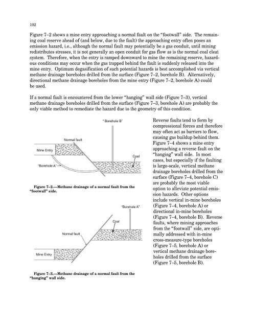
102Figure 7–2 shows a m<strong>in</strong>e entry approach<strong>in</strong>g a normal fault on the “footwall” side. The rema<strong>in</strong><strong>in</strong>gcoal reserve ahead of (and below, due to the fault) the approach<strong>in</strong>g entry often poses anemission hazard, i.e., although the normal fault may potentially be a gas conduit, until m<strong>in</strong><strong>in</strong>gredistributes stresses, it is not generally an open conduit <strong>for</strong> gas flow as is the normal coal cleatsystem. There<strong>for</strong>e, when the entry is ramped downward to m<strong>in</strong>e the rema<strong>in</strong><strong>in</strong>g reserve, hazardousconditions may occur when the gas trapped beh<strong>in</strong>d the fault is suddenly released <strong>in</strong>to them<strong>in</strong>e entry. Optimum degasification of such potential hazards is best accomplished via verticalmethane dra<strong>in</strong>age boreholes drilled from the surface (Figure 7–2, borehole B). Alternatively,directional methane dra<strong>in</strong>age boreholes from the m<strong>in</strong>e entry (Figure 7–2, borehole A) couldbe used.If a normal fault is encountered from the lower “hang<strong>in</strong>g” wall side (Figure 7–3), verticalmethane dra<strong>in</strong>age boreholes drilled from the surface (Figure 7–3, borehole A) are probably theonly viable method to remediate the hazard due to the geometry of this condition.Figure 7–2.—<strong>Methane</strong> dra<strong>in</strong>age of a normal fault from the“footwall” side.Reverse faults tend to <strong>for</strong>m bycompressional <strong>for</strong>ces and there<strong>for</strong>emay often act as barriers to flow,caus<strong>in</strong>g gas buildup beh<strong>in</strong>d them.Figure 7–4 shows a m<strong>in</strong>e entryapproach<strong>in</strong>g a reverse fault on the“hang<strong>in</strong>g” wall side. In mostcases, but especially if the fault<strong>in</strong>gis large-scale, vertical methanedra<strong>in</strong>age boreholes drilled from thesurface (Figure 7–4, borehole C)are probably the most viableoption to alleviate potential emissionhazards. Other options<strong>in</strong>clude vertical <strong>in</strong>-m<strong>in</strong>e boreholes(Figure 7–4, borehole A) ordirectional <strong>in</strong>-m<strong>in</strong>e boreholes(Figure 7–4, borehole B). Reversefaults, where m<strong>in</strong><strong>in</strong>g approachesfrom the “footwall” side, are optimallyaddressed with <strong>in</strong>-m<strong>in</strong>ecross-measure-type boreholes(Figure 7–5, borehole A) orvertical methane dra<strong>in</strong>age boreholesdrilled from the surface(Figure 7–5, borehole B).Figure 7–3.—<strong>Methane</strong> dra<strong>in</strong>age of a normal fault from the“hang<strong>in</strong>g” wall side.
- Page 1 and 2:
TMIC 9486Information Circular/2006H
- Page 3 and 4:
ORDERING INFORMATIONCopies of Natio
- Page 5 and 6:
ILLUSTRATIONS—ContinuedPage4-6. U
- Page 8:
HANDBOOK FOR METHANE CONTROL IN MIN
- Page 11 and 12:
4Below 5%, called the lower explosi
- Page 13 and 14:
6reduced pressure, except at very l
- Page 15 and 16:
8Static electricity. Protection aga
- Page 17 and 18:
10Figure 1-4.—Estimated methane c
- Page 19 and 20:
12LAYERING OF METHANE AT THE MINE R
- Page 21 and 22:
14good eyesight. 24methane level.Ot
- Page 23 and 24:
16a material balance indicated that
- Page 25 and 26:
18As an example, assume that themet
- Page 27 and 28:
20Figure 1-10.—Relative frequency
- Page 29 and 30:
22Davies AW, Isaac AK, Cook PM [200
- Page 31 and 32:
24Margerson SNA, Robinson H, Wilkin
- Page 33 and 34:
CHAPTER 2.—SAMPLING FOR METHANE I
- Page 35 and 36:
29USING PORTABLE METHANE DETECTORST
- Page 37 and 38:
Out-of-range gas concentrations in
- Page 39 and 40:
Figure 2-3.—Recorder chart from a
- Page 41 and 42:
35Industrial Scientific Corp. [2004
- Page 43 and 44:
38peaks, not the overallmethane lev
- Page 45 and 46:
40hung on J-hook assemblies, which
- Page 47 and 48:
42Methane dilution effectiveness.Th
- Page 49 and 50:
44found that effective scrubber ope
- Page 51 and 52:
46When the scrubber exhaust is not
- Page 53 and 54:
48Methane monitors are usually moun
- Page 55 and 56: 50to use radial bits instead of con
- Page 57 and 58: 52Mott ML, Chuhta EJ [1991]. Face v
- Page 59 and 60: 54Service, Centers for Disease Cont
- Page 61 and 62: 56Methane accumulationsaround thesh
- Page 63 and 64: 58corner and by 43% at supportNo. 4
- Page 65 and 66: 60When using water sprays to reduce
- Page 67 and 68: 62Cecala AB, Zimmer JA, Thimons ED
- Page 69 and 70: 64DESIGNING BLEEDER SYSTEMSAs part
- Page 71 and 72: 66Caved area characteristics. The c
- Page 73 and 74: 68then move this gas into the activ
- Page 75 and 76: 70perform tests to determine whethe
- Page 77 and 78: 72A major purpose of the bleeder sy
- Page 79 and 80: 74• Inlets to the pillared area n
- Page 81 and 82: 76REFERENCESCFR. Code of federal re
- Page 83 and 84: 78Methane is released into each min
- Page 85 and 86: 80Figure 6-1.—Gas content of coal
- Page 87 and 88: 82Figure 6-3.—Simplified illustra
- Page 89 and 90: 842. In-mine inclined or vertical b
- Page 91 and 92: 861. Packed cavity method and its v
- Page 93 and 94: 88Table 6-3.—Methane capture rati
- Page 95 and 96: 90Early experiences with this metho
- Page 97 and 98: 9211. At the surface installation (
- Page 99 and 100: 94• Estimated cost for moderately
- Page 101 and 102: 96Thakur PC [1981]. Methane control
- Page 103 and 104: 98Anomalous, unanticipated methane
- Page 105: 100Vertical methane drainage boreho
- Page 109 and 110: 104obvious solution to this problem
- Page 111 and 112: 106Figure 7-8.—Hypothetical gas c
- Page 113 and 114: 108Lama and Bodziony [1998] compile
- Page 115 and 116: 110In-mine methane drainage systems
- Page 117 and 118: 112Iannacchione AT, Ulery JP, Hyman
- Page 119 and 120: 114More sophisticated reservoir eng
- Page 121 and 122: 116coal lithotype on gas content is
- Page 123 and 124: 118FORECASTING REMAINING GAS-IN-PLA
- Page 125 and 126: 120⎛ y⎞⎜⎛⎞ ⎛ ⎞= ⎜
- Page 127 and 128: 122emissions. The geometry and size
- Page 129 and 130: 124Reservoir models require a subst
- Page 131 and 132: 126King GR, Ertekin T [1989a]. A su
- Page 133 and 134: 128an area of 314 ft 2 would requir
- Page 135 and 136: 130In the case of the abovementione
- Page 137 and 138: 132FILLING SHAFTS AT CLOSED MINESFi
- Page 139 and 140: 134Hinderfeld G [1995]. Ventilation
- Page 141 and 142: 136To calculate the effectiveinert,
- Page 143 and 144: 138exhaust. The remaining diesel ex
- Page 145 and 146: 140required only 4 min. As a result
- Page 147 and 148: 142Figure 11-1.—Desorption test a
- Page 149 and 150: 144enclosed in a tunnel-like struct
- Page 151 and 152: 146Kolada RJ [1985]. Investigation
- Page 153 and 154: 148air in a 6-ft by 9-ft by 6.5-ft
- Page 155 and 156: 150represents flammable mixtures. F
- Page 157 and 158:
152• In Eastern Europe, petroleum
- Page 159 and 160:
154Category II applies to domal sal
- Page 161 and 162:
1562. Monitoring for gas and taking
- Page 163 and 164:
158These mines typically have large
- Page 165 and 166:
160Dave Graham is the safety and he
- Page 167 and 168:
162Figure 13-2.—Examples of metha
- Page 169 and 170:
164REFERENCESAndrews JN [1987]. Nob
- Page 171 and 172:
166APPENDIX A.—ONTARIO OCCUPATION
- Page 174 and 175:
169CHAPTER 14.—PREVENTING METHANE
- Page 176 and 177:
Ways to confirm the presence of gas
- Page 178 and 179:
173The tunnel face is usually venti
- Page 180 and 181:
175Figure 14-5.—TBM ventilation s
- Page 182 and 183:
face. While one of these elements a
- Page 184 and 185:
179ELIMINATING IGNITION SOURCESElec
- Page 186 and 187:
181INDEXAAbnormally gassy faces....
- Page 188 and 189:
183NNatural ventilation, coal silos
- Page 190 and 191:
Delivering on the Nation’s Promis