Handbook for Methane Control in Mining - AMMSA
Handbook for Methane Control in Mining - AMMSA
Handbook for Methane Control in Mining - AMMSA

Create successful ePaper yourself
Turn your PDF publications into a flip-book with our unique Google optimized e-Paper software.
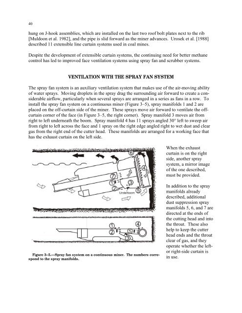
40hung on J-hook assemblies, which are <strong>in</strong>stalled on the last two roof bolt plates next to the rib[Muldoon et al. 1982], and the pipe is slid <strong>for</strong>ward as the m<strong>in</strong>er advances. Urosek et al. [1988]described 11 extensible l<strong>in</strong>e curta<strong>in</strong> systems used <strong>in</strong> coal m<strong>in</strong>es.Despite the development of extensible curta<strong>in</strong> systems, the cont<strong>in</strong>u<strong>in</strong>g need <strong>for</strong> better methanecontrol has led to improved face ventilation systems us<strong>in</strong>g spray fan and scrubber systems.VENTILATION WITH THE SPRAY FAN SYSTEMThe spray fan system is an auxiliary ventilation system that makes use of the air-mov<strong>in</strong>g abilityof water sprays. Mov<strong>in</strong>g droplets <strong>in</strong> the spray drag the surround<strong>in</strong>g air <strong>for</strong>ward to create a considerableairflow, particularly when several sprays are arranged <strong>in</strong> a series as fans <strong>in</strong> a row. To<strong>in</strong>stall the spray fan system on a cont<strong>in</strong>uous m<strong>in</strong>er (Figure 3–5), spray manifolds 1 and 2 areplaced on the off-curta<strong>in</strong> side of the m<strong>in</strong>er. These sprays move air <strong>for</strong>ward to ventilate the offcurta<strong>in</strong>corner of the face (<strong>in</strong> Figure 3–5, the right corner). Spray manifold 3 moves air fromright to left underneath the boom. Spray manifold 4 has 11 sprays angled 30° left to sweep airfrom right to left across the face and 1 spray on the right edge angled right to wet dust and cleargas from the right end of the cutter head. These manifolds are arranged <strong>for</strong> a work<strong>in</strong>g face thathas the exhaust curta<strong>in</strong> on the left side.When the exhaustcurta<strong>in</strong> is on the rightside, another spraysystem, a mirror imageof the one described,must be provided.Figure 3–5.—Spray fan system on a cont<strong>in</strong>uous m<strong>in</strong>er. The numbers correspondto the spray manifolds.In addition to the spraymanifolds alreadydescribed, additionaldust suppression spraymanifolds 5, 6, and 7 aredirected at the ends ofthe cutt<strong>in</strong>g head and <strong>in</strong>tothe throat. These alsohelp to keep the cutterhead ends and the throatclear of gas, and theyoperate whether the leftorright-side curta<strong>in</strong> is<strong>in</strong> use.