Handbook for Methane Control in Mining - AMMSA
Handbook for Methane Control in Mining - AMMSA
Handbook for Methane Control in Mining - AMMSA

Create successful ePaper yourself
Turn your PDF publications into a flip-book with our unique Google optimized e-Paper software.
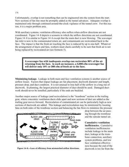
176Un<strong>for</strong>tunately, overlap is not someth<strong>in</strong>g that can be eng<strong>in</strong>eered <strong>in</strong>to the system from the start.New sections of fan l<strong>in</strong>e must be promptly added as the tunnel advances. Adequate overlap isma<strong>in</strong>ta<strong>in</strong>ed only through cont<strong>in</strong>ued around-the-clock vigilance of the tunnel crew. For this reason,it is a major problem area.With auxiliary systems, ventilation efficiency also suffers when airflow directions are notcoord<strong>in</strong>ated. Figure 14–8 depicts a scenario <strong>in</strong> which the airflow directions are not coord<strong>in</strong>ated.Figure 14–8 is similar to Figure 14–6 except that the ma<strong>in</strong> duct is now blow<strong>in</strong>g. The scavengerfan <strong>in</strong>let is now <strong>in</strong> the contam<strong>in</strong>ated return air, and contam<strong>in</strong>ants are recirculated back to theface. The impact is that the fresh air reach<strong>in</strong>g the face is reduced by up to one-half. Whateverthe arrangement of ducts and fans, workers must check carefully to be sure that fresh air is notbe<strong>in</strong>g replaced by recirculated air (see footnote 5).A scavenger fan with <strong>in</strong>adequate overlap can recirculate 90% of the airreturn<strong>in</strong>g from the face. In such an <strong>in</strong>stance, a 3,000-cfm scavenger fanwill deliver only 10% or 300 cfm of fresh air to the face.M<strong>in</strong>imiz<strong>in</strong>g leakage. Leakage <strong>in</strong> both ma<strong>in</strong> and face ventilation systems is another source ofairflow losses. Factors that impact leakage are fan placement, ductwork diameter and length,pressure drop, and duct condition. It is not unusual to lose half of the airflow <strong>in</strong> a long run ofductwork. In plann<strong>in</strong>g, the largest practical diameter of duct should be used. Damaged ductworkshould never be <strong>in</strong>stalled, particularly if the ends are buckled.Another major source of leakage (and recirculation) is the “trombone” section <strong>in</strong> the trail<strong>in</strong>ggear, where concentric ventilation ducts slide apart and new sections of duct are added as thetrail<strong>in</strong>g gear moves <strong>for</strong>ward. Recirculation of contam<strong>in</strong>ated air can be particularly high as newsections of ductwork are added. This leakage and recirculation may be m<strong>in</strong>imized by locat<strong>in</strong>gfans on both sides of the trombone section and balanc<strong>in</strong>g the fan flows to m<strong>in</strong>imize the pressuredrop between the air pass<strong>in</strong>gthrough the tromboneand the outside tunnel air.Figure 14–8.—Loss of efficiency from mismatched airflow directions.Cumulative ventilation<strong>in</strong>efficiencies. Cumulativeventilation <strong>in</strong>efficiencies<strong>in</strong>clude leakage <strong>in</strong> the ma<strong>in</strong>duct, leakage at the tromboneconnection, auxiliarysystem problems, and lowface ventilation effectivenessbecause the end of theductwork is too far from the