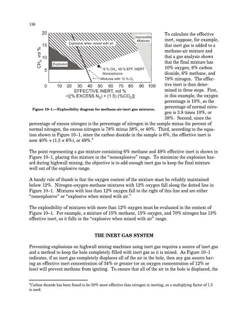
135CHAPTER 10.—METHANE CONTROL IN HIGHWALL MININGBy Jon C. Volkwe<strong>in</strong> 1 and Fred N. Kissell, Ph.D. 2In This Chapter How <strong>in</strong>ert gas works to prevent methane explosions How <strong>in</strong>ert gas is generated and delivered at highwall m<strong>in</strong>es Volume and quality requirements <strong>for</strong> <strong>in</strong>ert gas at highwall m<strong>in</strong>es How an <strong>in</strong>ert gas system is operatedand Precautions to take dur<strong>in</strong>g m<strong>in</strong><strong>in</strong>g to prevent methane explosionsThis chapter discusses a method, orig<strong>in</strong>ally developed by Volkwe<strong>in</strong> and Ulery [1993], to preventmethane explosions dur<strong>in</strong>g highwall m<strong>in</strong><strong>in</strong>g. In highwall m<strong>in</strong><strong>in</strong>g, a horizontal auger or a m<strong>in</strong><strong>in</strong>gmach<strong>in</strong>e enters the coal seam from a surface m<strong>in</strong>e pit at the bottom of a highwall, and the coal ism<strong>in</strong>ed out from a series of parallel holes. Explosions can be prevented by <strong>in</strong>ject<strong>in</strong>g <strong>in</strong>ert gas <strong>in</strong>toeach hole as it is m<strong>in</strong>ed.Coal near the surface has lost most of its methane gas over time. However, <strong>in</strong> recent years,surface m<strong>in</strong><strong>in</strong>g has been used <strong>for</strong> deeper reserves of coal. This trend toward m<strong>in</strong><strong>in</strong>g deeperreserves has <strong>in</strong>creased the chance of encounter<strong>in</strong>g methane, and methane explosions at highwallm<strong>in</strong><strong>in</strong>g operations have resulted <strong>in</strong> <strong>in</strong>juries.HOW INERT GAS WORKS TO PREVENT METHANE EXPLOSIONSA methane explosion requires the presence of sufficient amounts of both methane and oxygen,as well as an ignition source. If the methane cannot be reduced and the ignition source cannot beelim<strong>in</strong>ated, then explosions may be prevented by add<strong>in</strong>g an <strong>in</strong>ert gas, which conta<strong>in</strong>s little to nooxygen, to the mixture [FWQA 1970]. Just how much <strong>in</strong>ert gas must be added depends on them<strong>in</strong><strong>in</strong>g rate, as well as the composition of the <strong>in</strong>ert gas.An explosibility diagram can be used to show whether a methane mixture is explosive after <strong>in</strong>ertgas is added [Zabetakis et al. 1959] (Figure 10–1). This diagram <strong>in</strong>dicates that gas mixturesfall <strong>in</strong>to one of three range categories—explosive, explosive when mixed with air, andnonexplosive—depend<strong>in</strong>g on the percentage of methane and percentage of “effective <strong>in</strong>ert.”Effective <strong>in</strong>ert is calculated from the percentage of “excess nitrogen” 3 and percentage of carbondioxide <strong>in</strong> the mixture.1 Research physical scientist, Pittsburgh Research Laboratory, National Institute <strong>for</strong> Occupational Safety and Health,Pittsburgh, PA.2 Research physical scientist, Pittsburgh Research Laboratory, National Institute <strong>for</strong> Occupational Safety and Health,Pittsburgh, PA (retired).3 The percentage of excess nitrogen is the percentage of nitrogen <strong>in</strong> the sample m<strong>in</strong>us the percentage of “normalnitrogen.” Normal nitrogen is calculated from the ratio of nitrogen to oxygen normally found <strong>in</strong> air—a factor of 3.8.
136To calculate the effective<strong>in</strong>ert, suppose, <strong>for</strong> example,that <strong>in</strong>ert gas is added to amethane-air mixture andthat a gas analysis showsthat the f<strong>in</strong>al mixture has10% oxygen, 6% carbondioxide, 6% methane, and78% nitrogen. The effective<strong>in</strong>ert is then determ<strong>in</strong>ed<strong>in</strong> three steps. First,<strong>in</strong> this example, the oxygenpercentage is 10%, so thepercentage of normal nitrogenis 3.8 times 10%, orFigure 10–1.—Explosibility diagram <strong>for</strong> methane-air-<strong>in</strong>ert gas mixtures.38%. Second, s<strong>in</strong>ce thepercentage of excess nitrogen is the percentage of nitrogen <strong>in</strong> the sample m<strong>in</strong>us the percent ofnormal nitrogen, the excess nitrogen is 78% m<strong>in</strong>us 38%, or 40%. Third, accord<strong>in</strong>g to the equationshown <strong>in</strong> Figure 10–1, s<strong>in</strong>ce the carbon dioxide <strong>in</strong> the sample is 6%, the effective <strong>in</strong>ert isnow 40% + (1.5 × 6%), or 49%. 4The po<strong>in</strong>t represent<strong>in</strong>g a gas mixture conta<strong>in</strong><strong>in</strong>g 6% methane and 49% effective <strong>in</strong>ert is shown <strong>in</strong>Figure 10–1, plac<strong>in</strong>g this mixture <strong>in</strong> the “nonexplosive” range. To m<strong>in</strong>imize the explosion hazarddur<strong>in</strong>g highwall m<strong>in</strong><strong>in</strong>g, the objective is to add enough <strong>in</strong>ert gas to keep the f<strong>in</strong>al mixturewell out of the explosive range.A handy rule of thumb is that the oxygen content of the mixture must be reliably ma<strong>in</strong>ta<strong>in</strong>edbelow 12%. Nitrogen-oxygen-methane mixtures with 12% oxygen fall along the dotted l<strong>in</strong>e <strong>in</strong>Figure 10–1. Mixtures with less than 12% oxygen fall to the right of this l<strong>in</strong>e and are either“nonexplosive” or “explosive when mixed with air.”The explosibility of mixtures with more than 12% oxygen must be evaluated <strong>in</strong> the context ofFigure 10–1. For example, a mixture of 15% methane, 15% oxygen, and 70% nitrogen has 13%effective <strong>in</strong>ert, so it falls <strong>in</strong> the “explosive when mixed with air” range.THE INERT GAS SYSTEMPrevent<strong>in</strong>g explosions on highwall m<strong>in</strong><strong>in</strong>g mach<strong>in</strong>es us<strong>in</strong>g <strong>in</strong>ert gas requires a source of <strong>in</strong>ert gasand a method to keep the hole completely filled with <strong>in</strong>ert gas as it is m<strong>in</strong>ed. As Figure 10–1<strong>in</strong>dicates, if an <strong>in</strong>ert gas completely displaces all of the air <strong>in</strong> the hole, then any gas source hav<strong>in</strong>gan effective <strong>in</strong>ert concentration of 34% or greater (or an oxygen concentration of 12% orless) will prevent methane from ignit<strong>in</strong>g. To ensure that all of the air <strong>in</strong> the hole is displaced, the4 Carbon dioxide has been found to be 50% more effective than nitrogen <strong>in</strong> <strong>in</strong>ert<strong>in</strong>g, so a multiply<strong>in</strong>g factor of 1.5is used.
- Page 1 and 2:
TMIC 9486Information Circular/2006H
- Page 3 and 4:
ORDERING INFORMATIONCopies of Natio
- Page 5 and 6:
ILLUSTRATIONS—ContinuedPage4-6. U
- Page 8:
HANDBOOK FOR METHANE CONTROL IN MIN
- Page 11 and 12:
4Below 5%, called the lower explosi
- Page 13 and 14:
6reduced pressure, except at very l
- Page 15 and 16:
8Static electricity. Protection aga
- Page 17 and 18:
10Figure 1-4.—Estimated methane c
- Page 19 and 20:
12LAYERING OF METHANE AT THE MINE R
- Page 21 and 22:
14good eyesight. 24methane level.Ot
- Page 23 and 24:
16a material balance indicated that
- Page 25 and 26:
18As an example, assume that themet
- Page 27 and 28:
20Figure 1-10.—Relative frequency
- Page 29 and 30:
22Davies AW, Isaac AK, Cook PM [200
- Page 31 and 32:
24Margerson SNA, Robinson H, Wilkin
- Page 33 and 34:
CHAPTER 2.—SAMPLING FOR METHANE I
- Page 35 and 36:
29USING PORTABLE METHANE DETECTORST
- Page 37 and 38:
Out-of-range gas concentrations in
- Page 39 and 40:
Figure 2-3.—Recorder chart from a
- Page 41 and 42:
35Industrial Scientific Corp. [2004
- Page 43 and 44:
38peaks, not the overallmethane lev
- Page 45 and 46:
40hung on J-hook assemblies, which
- Page 47 and 48:
42Methane dilution effectiveness.Th
- Page 49 and 50:
44found that effective scrubber ope
- Page 51 and 52:
46When the scrubber exhaust is not
- Page 53 and 54:
48Methane monitors are usually moun
- Page 55 and 56:
50to use radial bits instead of con
- Page 57 and 58:
52Mott ML, Chuhta EJ [1991]. Face v
- Page 59 and 60:
54Service, Centers for Disease Cont
- Page 61 and 62:
56Methane accumulationsaround thesh
- Page 63 and 64:
58corner and by 43% at supportNo. 4
- Page 65 and 66:
60When using water sprays to reduce
- Page 67 and 68:
62Cecala AB, Zimmer JA, Thimons ED
- Page 69 and 70:
64DESIGNING BLEEDER SYSTEMSAs part
- Page 71 and 72:
66Caved area characteristics. The c
- Page 73 and 74:
68then move this gas into the activ
- Page 75 and 76:
70perform tests to determine whethe
- Page 77 and 78:
72A major purpose of the bleeder sy
- Page 79 and 80:
74• Inlets to the pillared area n
- Page 81 and 82:
76REFERENCESCFR. Code of federal re
- Page 83 and 84:
78Methane is released into each min
- Page 85 and 86:
80Figure 6-1.—Gas content of coal
- Page 87 and 88:
82Figure 6-3.—Simplified illustra
- Page 89 and 90: 842. In-mine inclined or vertical b
- Page 91 and 92: 861. Packed cavity method and its v
- Page 93 and 94: 88Table 6-3.—Methane capture rati
- Page 95 and 96: 90Early experiences with this metho
- Page 97 and 98: 9211. At the surface installation (
- Page 99 and 100: 94• Estimated cost for moderately
- Page 101 and 102: 96Thakur PC [1981]. Methane control
- Page 103 and 104: 98Anomalous, unanticipated methane
- Page 105 and 106: 100Vertical methane drainage boreho
- Page 107 and 108: 102Figure 7-2 shows a mine entry ap
- Page 109 and 110: 104obvious solution to this problem
- Page 111 and 112: 106Figure 7-8.—Hypothetical gas c
- Page 113 and 114: 108Lama and Bodziony [1998] compile
- Page 115 and 116: 110In-mine methane drainage systems
- Page 117 and 118: 112Iannacchione AT, Ulery JP, Hyman
- Page 119 and 120: 114More sophisticated reservoir eng
- Page 121 and 122: 116coal lithotype on gas content is
- Page 123 and 124: 118FORECASTING REMAINING GAS-IN-PLA
- Page 125 and 126: 120⎛ y⎞⎜⎛⎞ ⎛ ⎞= ⎜
- Page 127 and 128: 122emissions. The geometry and size
- Page 129 and 130: 124Reservoir models require a subst
- Page 131 and 132: 126King GR, Ertekin T [1989a]. A su
- Page 133 and 134: 128an area of 314 ft 2 would requir
- Page 135 and 136: 130In the case of the abovementione
- Page 137 and 138: 132FILLING SHAFTS AT CLOSED MINESFi
- Page 139: 134Hinderfeld G [1995]. Ventilation
- Page 143 and 144: 138exhaust. The remaining diesel ex
- Page 145 and 146: 140required only 4 min. As a result
- Page 147 and 148: 142Figure 11-1.—Desorption test a
- Page 149 and 150: 144enclosed in a tunnel-like struct
- Page 151 and 152: 146Kolada RJ [1985]. Investigation
- Page 153 and 154: 148air in a 6-ft by 9-ft by 6.5-ft
- Page 155 and 156: 150represents flammable mixtures. F
- Page 157 and 158: 152• In Eastern Europe, petroleum
- Page 159 and 160: 154Category II applies to domal sal
- Page 161 and 162: 1562. Monitoring for gas and taking
- Page 163 and 164: 158These mines typically have large
- Page 165 and 166: 160Dave Graham is the safety and he
- Page 167 and 168: 162Figure 13-2.—Examples of metha
- Page 169 and 170: 164REFERENCESAndrews JN [1987]. Nob
- Page 171 and 172: 166APPENDIX A.—ONTARIO OCCUPATION
- Page 174 and 175: 169CHAPTER 14.—PREVENTING METHANE
- Page 176 and 177: Ways to confirm the presence of gas
- Page 178 and 179: 173The tunnel face is usually venti
- Page 180 and 181: 175Figure 14-5.—TBM ventilation s
- Page 182 and 183: face. While one of these elements a
- Page 184 and 185: 179ELIMINATING IGNITION SOURCESElec
- Page 186 and 187: 181INDEXAAbnormally gassy faces....
- Page 188 and 189: 183NNatural ventilation, coal silos
- Page 190 and 191:
Delivering on the Nation’s Promis