Handbook for Methane Control in Mining - AMMSA
Handbook for Methane Control in Mining - AMMSA
Handbook for Methane Control in Mining - AMMSA

Create successful ePaper yourself
Turn your PDF publications into a flip-book with our unique Google optimized e-Paper software.
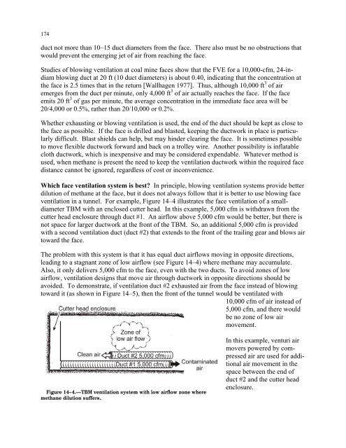
174duct not more than 10–15 duct diameters from the face. There also must be no obstructions thatwould prevent the emerg<strong>in</strong>g jet of air from reach<strong>in</strong>g the face.Studies of blow<strong>in</strong>g ventilation at coal m<strong>in</strong>e faces show that the FVE <strong>for</strong> a 10,000-cfm, 24-<strong>in</strong>diamblow<strong>in</strong>g duct at 20 ft (10 duct diameters) is about 0.40, <strong>in</strong>dicat<strong>in</strong>g that the concentration atthe face is 2.5 times that <strong>in</strong> the return [Wallhagen 1977]. Thus, although 10,000 ft 3 of airemerges from the duct per m<strong>in</strong>ute, only 4,000 ft 3 of air actually reaches the face. If the faceemits 20 ft 3 of gas per m<strong>in</strong>ute, the average concentration <strong>in</strong> the immediate face area will be20/4,000 or 0.5%, rather than 20/10,000 or 0.2%.Whether exhaust<strong>in</strong>g or blow<strong>in</strong>g ventilation is used, the end of the duct should be kept as close tothe face as possible. If the face is drilled and blasted, keep<strong>in</strong>g the ductwork <strong>in</strong> place is particularlydifficult. Blast shields can help, but may h<strong>in</strong>der clear<strong>in</strong>g the face. It is sometimes possibleto move flexible ductwork <strong>for</strong>ward and back on a trolley wire. Another possibility is <strong>in</strong>flatablecloth ductwork, which is <strong>in</strong>expensive and may be considered expendable. Whatever method isused, when methane is present the need to keep the ventilation ductwork with<strong>in</strong> the required facedistance cannot be ignored, regardless of cost or <strong>in</strong>convenience.Which face ventilation system is best? In pr<strong>in</strong>ciple, blow<strong>in</strong>g ventilation systems provide betterdilution of methane at the face, but it does not always follow that it is better to use blow<strong>in</strong>g faceventilation <strong>in</strong> a tunnel. For example, Figure 14–4 illustrates the face ventilation of a smalldiameterTBM with an enclosed cutter head. In this example, 5,000 cfm is withdrawn from thecutter head enclosure through duct #1. An airflow above 5,000 cfm would be better, but there isnot space <strong>for</strong> larger ductwork at the front of the TBM. So, an additional 5,000 cfm is providedwith a second ventilation duct (duct #2) that extends to the front of the trail<strong>in</strong>g gear and blows airtoward the face.The problem with this system is that it has equal duct airflows mov<strong>in</strong>g <strong>in</strong> opposite directions,lead<strong>in</strong>g to a stagnant zone of low airflow (see Figure 14–4) where methane may accumulate.Also, it only delivers 5,000 cfm to the face, even with the two ducts. To avoid zones of lowairflow, ventilation designs that move air through ductwork <strong>in</strong> opposite directions should beavoided. To demonstrate, if ventilation duct #2 exhausted air from the face <strong>in</strong>stead of blow<strong>in</strong>gtoward it (as shown <strong>in</strong> Figure 14–5), then the front of the tunnel would be ventilated with10,000 cfm of air <strong>in</strong>stead of5,000 cfm, and there wouldbe no zone of low airmovement.Figure 14–4.—TBM ventilation system with low airflow zone wheremethane dilution suffers.In this example, venturi airmovers powered by compressedair are used <strong>for</strong> additionalair movement <strong>in</strong> thespace between the end ofduct #2 and the cutter headenclosure.