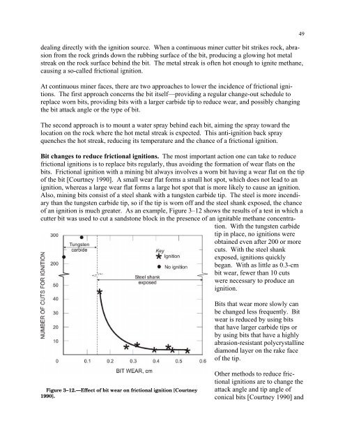
deal<strong>in</strong>g directly with the ignition source. When a cont<strong>in</strong>uous m<strong>in</strong>er cutter bit strikes rock, abrasionfrom the rock gr<strong>in</strong>ds down the rubb<strong>in</strong>g surface of the bit, produc<strong>in</strong>g a glow<strong>in</strong>g hot metalstreak on the rock surface beh<strong>in</strong>d the bit. The metal streak is often hot enough to ignite methane,caus<strong>in</strong>g a so-called frictional ignition.At cont<strong>in</strong>uous m<strong>in</strong>er faces, there are two approaches to lower the <strong>in</strong>cidence of frictional ignitions.The first approach concerns the bit itself—provid<strong>in</strong>g a regular change-out schedule toreplace worn bits, provid<strong>in</strong>g bits with a larger carbide tip to reduce wear, and possibly chang<strong>in</strong>gthe bit attack angle or the type of bit.The second approach is to mount a water spray beh<strong>in</strong>d each bit, aim<strong>in</strong>g the spray toward thelocation on the rock where the hot metal streak is expected. This anti-ignition back sprayquenches the hot streak, reduc<strong>in</strong>g its temperature and the chance of a frictional ignition.Bit changes to reduce frictional ignitions. The most important action one can take to reducefrictional ignitions is to replace bits regularly, thus avoid<strong>in</strong>g the <strong>for</strong>mation of wear flats on thebits. Frictional ignition with a m<strong>in</strong><strong>in</strong>g bit always <strong>in</strong>volves a worn bit hav<strong>in</strong>g a wear flat on the tipof the bit [Courtney 1990]. A small wear flat <strong>for</strong>ms a small hot spot, which does not lead to anignition, whereas a large wear flat <strong>for</strong>ms a large hot spot that is more likely to cause an ignition.Also, m<strong>in</strong><strong>in</strong>g bits consist of a steel shank with a tungsten carbide tip. The steel is more <strong>in</strong>cendiarythan the tungsten carbide tip, so if the tip is worn off and the steel shank exposed, the chanceof an ignition is much greater. As an example, Figure 3–12 shows the results of a test <strong>in</strong> which acutter bit was used to cut a sandstone block <strong>in</strong> the presence of an ignitable methane concentration.With the tungsten carbidetip <strong>in</strong> place, no ignitions wereobta<strong>in</strong>ed even after 200 or morecuts. With the steel shankexposed, ignitions quicklybegan. With as little as 0.3-cmbit wear, fewer than 10 cutswere necessary to produce anignition.49Bits that wear more slowly canbe changed less frequently. Bitwear is reduced by us<strong>in</strong>g bitsthat have larger carbide tips orby us<strong>in</strong>g bits that have a highlyabrasion-resistant polycrystall<strong>in</strong>ediamond layer on the rake faceof the tip.Figure 3–12.—Effect of bit wear on frictional ignition [Courtney1990].Other methods to reduce frictionalignitions are to change theattack angle and tip angle ofconical bits [Courtney 1990] and
50to use radial bits <strong>in</strong>stead of conical bits [Phillips 1996]. McNider et al. [1987] reported adecrease <strong>in</strong> frictional ignitions by us<strong>in</strong>g bits with larger carbide tips and by chang<strong>in</strong>g the bitattack angle. 17Anti-ignition back sprays. Anti-ignition back sprays, an effective method to reduce frictionalignitions, are discussed <strong>in</strong> the longwall chapter (Chapter 4). Br<strong>in</strong>g<strong>in</strong>g water to the cutter headon cont<strong>in</strong>uous m<strong>in</strong>ers has been an eng<strong>in</strong>eer<strong>in</strong>g challenge. However, <strong>in</strong> recent years, practical(if expensive) water seals <strong>for</strong> cont<strong>in</strong>uous m<strong>in</strong>er heads have been developed. As a result, a few“wet-head” cont<strong>in</strong>uous m<strong>in</strong>ers equipped with anti-ignition back sprays have been <strong>in</strong>stalled <strong>in</strong>U.S. coal m<strong>in</strong>es with a history of frictional ignition problems. Phillips [1997] has provided astatus report on wet-head cutt<strong>in</strong>g drums.A thorough review of frictional ignitions <strong>in</strong> m<strong>in</strong>es,<strong>in</strong>clud<strong>in</strong>g metal-to-metal ignitions and those fromroof falls, is provided by Phillips [1996].REFERENCES68 Fed. Reg. 40132 [2003]. M<strong>in</strong>e Safety and Health Adm<strong>in</strong>istration, 30 CFR Part 75: improv<strong>in</strong>gand elim<strong>in</strong>at<strong>in</strong>g regulations, phase 5, miscellaneous technology improvements (methane test<strong>in</strong>g);f<strong>in</strong>al rule.Campbell CD, Dupree WA [1991]. Evaluation of methane dilution capacity of a blow<strong>in</strong>g faceventilation system us<strong>in</strong>g a water spray fan and dust scrubber. In: Proceed<strong>in</strong>gs of the Fifth U.S.M<strong>in</strong>e Ventilation Symposium (Morgantown, WV, June 3–5, 1991).CFR. Code of federal regulations. Wash<strong>in</strong>gton DC: U.S. Government Pr<strong>in</strong>t<strong>in</strong>g Office, Office ofthe Federal Register.Courtney WG [1990]. Frictional ignition with coal m<strong>in</strong><strong>in</strong>g bits. Pittsburgh, PA: U.S. Departmentof the Interior, Bureau of M<strong>in</strong>es, IC 9251. NTIS No. PB91110072.Denk JM, Smith GE, Stoltz RT [1989]. Face ventilation <strong>in</strong>vestigation: Wabash m<strong>in</strong>e, I.D. No.11–00877, AMAX Coal Company, Keensburg, Wabash County, Ill<strong>in</strong>ois, August 29, 1989-September 1, 1989. Pittsburgh, PA: U.S. Department of Labor, M<strong>in</strong>e Safety and Health Adm<strong>in</strong>istration,Pittsburgh Health Technology Center, Ventilation Division, Investigative ReportNo. P313–V218.Denk JM, Younger RK, Mott ML, Chuhta EJ [1988]. Face ventilation <strong>in</strong>vestigations: Mary LeeNo. 1 m<strong>in</strong>e, I.D. No. 01–00515–0, Drummond Company, Incorporated, Goodspr<strong>in</strong>gs, WalkerCounty, Alabama, October 28-November 4, 1987, and October 18–26, 1988. Pittsburgh, PA:17 Chang<strong>in</strong>g the bit attack angle can also raise the cutt<strong>in</strong>g <strong>for</strong>ce, requir<strong>in</strong>g a change <strong>in</strong> drum design.
- Page 1 and 2:
TMIC 9486Information Circular/2006H
- Page 3 and 4: ORDERING INFORMATIONCopies of Natio
- Page 5 and 6: ILLUSTRATIONS—ContinuedPage4-6. U
- Page 8: HANDBOOK FOR METHANE CONTROL IN MIN
- Page 11 and 12: 4Below 5%, called the lower explosi
- Page 13 and 14: 6reduced pressure, except at very l
- Page 15 and 16: 8Static electricity. Protection aga
- Page 17 and 18: 10Figure 1-4.—Estimated methane c
- Page 19 and 20: 12LAYERING OF METHANE AT THE MINE R
- Page 21 and 22: 14good eyesight. 24methane level.Ot
- Page 23 and 24: 16a material balance indicated that
- Page 25 and 26: 18As an example, assume that themet
- Page 27 and 28: 20Figure 1-10.—Relative frequency
- Page 29 and 30: 22Davies AW, Isaac AK, Cook PM [200
- Page 31 and 32: 24Margerson SNA, Robinson H, Wilkin
- Page 33 and 34: CHAPTER 2.—SAMPLING FOR METHANE I
- Page 35 and 36: 29USING PORTABLE METHANE DETECTORST
- Page 37 and 38: Out-of-range gas concentrations in
- Page 39 and 40: Figure 2-3.—Recorder chart from a
- Page 41 and 42: 35Industrial Scientific Corp. [2004
- Page 43 and 44: 38peaks, not the overallmethane lev
- Page 45 and 46: 40hung on J-hook assemblies, which
- Page 47 and 48: 42Methane dilution effectiveness.Th
- Page 49 and 50: 44found that effective scrubber ope
- Page 51 and 52: 46When the scrubber exhaust is not
- Page 53: 48Methane monitors are usually moun
- Page 57 and 58: 52Mott ML, Chuhta EJ [1991]. Face v
- Page 59 and 60: 54Service, Centers for Disease Cont
- Page 61 and 62: 56Methane accumulationsaround thesh
- Page 63 and 64: 58corner and by 43% at supportNo. 4
- Page 65 and 66: 60When using water sprays to reduce
- Page 67 and 68: 62Cecala AB, Zimmer JA, Thimons ED
- Page 69 and 70: 64DESIGNING BLEEDER SYSTEMSAs part
- Page 71 and 72: 66Caved area characteristics. The c
- Page 73 and 74: 68then move this gas into the activ
- Page 75 and 76: 70perform tests to determine whethe
- Page 77 and 78: 72A major purpose of the bleeder sy
- Page 79 and 80: 74• Inlets to the pillared area n
- Page 81 and 82: 76REFERENCESCFR. Code of federal re
- Page 83 and 84: 78Methane is released into each min
- Page 85 and 86: 80Figure 6-1.—Gas content of coal
- Page 87 and 88: 82Figure 6-3.—Simplified illustra
- Page 89 and 90: 842. In-mine inclined or vertical b
- Page 91 and 92: 861. Packed cavity method and its v
- Page 93 and 94: 88Table 6-3.—Methane capture rati
- Page 95 and 96: 90Early experiences with this metho
- Page 97 and 98: 9211. At the surface installation (
- Page 99 and 100: 94• Estimated cost for moderately
- Page 101 and 102: 96Thakur PC [1981]. Methane control
- Page 103 and 104: 98Anomalous, unanticipated methane
- Page 105 and 106:
100Vertical methane drainage boreho
- Page 107 and 108:
102Figure 7-2 shows a mine entry ap
- Page 109 and 110:
104obvious solution to this problem
- Page 111 and 112:
106Figure 7-8.—Hypothetical gas c
- Page 113 and 114:
108Lama and Bodziony [1998] compile
- Page 115 and 116:
110In-mine methane drainage systems
- Page 117 and 118:
112Iannacchione AT, Ulery JP, Hyman
- Page 119 and 120:
114More sophisticated reservoir eng
- Page 121 and 122:
116coal lithotype on gas content is
- Page 123 and 124:
118FORECASTING REMAINING GAS-IN-PLA
- Page 125 and 126:
120⎛ y⎞⎜⎛⎞ ⎛ ⎞= ⎜
- Page 127 and 128:
122emissions. The geometry and size
- Page 129 and 130:
124Reservoir models require a subst
- Page 131 and 132:
126King GR, Ertekin T [1989a]. A su
- Page 133 and 134:
128an area of 314 ft 2 would requir
- Page 135 and 136:
130In the case of the abovementione
- Page 137 and 138:
132FILLING SHAFTS AT CLOSED MINESFi
- Page 139 and 140:
134Hinderfeld G [1995]. Ventilation
- Page 141 and 142:
136To calculate the effectiveinert,
- Page 143 and 144:
138exhaust. The remaining diesel ex
- Page 145 and 146:
140required only 4 min. As a result
- Page 147 and 148:
142Figure 11-1.—Desorption test a
- Page 149 and 150:
144enclosed in a tunnel-like struct
- Page 151 and 152:
146Kolada RJ [1985]. Investigation
- Page 153 and 154:
148air in a 6-ft by 9-ft by 6.5-ft
- Page 155 and 156:
150represents flammable mixtures. F
- Page 157 and 158:
152• In Eastern Europe, petroleum
- Page 159 and 160:
154Category II applies to domal sal
- Page 161 and 162:
1562. Monitoring for gas and taking
- Page 163 and 164:
158These mines typically have large
- Page 165 and 166:
160Dave Graham is the safety and he
- Page 167 and 168:
162Figure 13-2.—Examples of metha
- Page 169 and 170:
164REFERENCESAndrews JN [1987]. Nob
- Page 171 and 172:
166APPENDIX A.—ONTARIO OCCUPATION
- Page 174 and 175:
169CHAPTER 14.—PREVENTING METHANE
- Page 176 and 177:
Ways to confirm the presence of gas
- Page 178 and 179:
173The tunnel face is usually venti
- Page 180 and 181:
175Figure 14-5.—TBM ventilation s
- Page 182 and 183:
face. While one of these elements a
- Page 184 and 185:
179ELIMINATING IGNITION SOURCESElec
- Page 186 and 187:
181INDEXAAbnormally gassy faces....
- Page 188 and 189:
183NNatural ventilation, coal silos
- Page 190 and 191:
Delivering on the Nation’s Promis