Handbook for Methane Control in Mining - AMMSA
Handbook for Methane Control in Mining - AMMSA
Handbook for Methane Control in Mining - AMMSA

You also want an ePaper? Increase the reach of your titles
YUMPU automatically turns print PDFs into web optimized ePapers that Google loves.
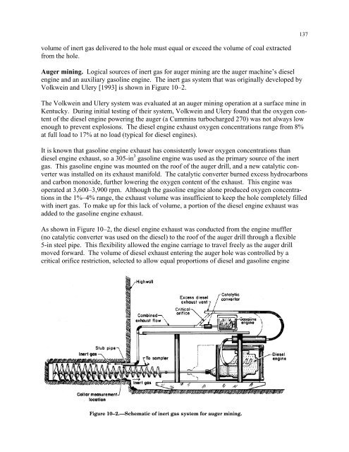
137volume of <strong>in</strong>ert gas delivered to the hole must equal or exceed the volume of coal extractedfrom the hole.Auger m<strong>in</strong><strong>in</strong>g. Logical sources of <strong>in</strong>ert gas <strong>for</strong> auger m<strong>in</strong><strong>in</strong>g are the auger mach<strong>in</strong>e’s dieseleng<strong>in</strong>e and an auxiliary gasol<strong>in</strong>e eng<strong>in</strong>e. The <strong>in</strong>ert gas system that was orig<strong>in</strong>ally developed byVolkwe<strong>in</strong> and Ulery [1993] is shown <strong>in</strong> Figure 10–2.The Volkwe<strong>in</strong> and Ulery system was evaluated at an auger m<strong>in</strong><strong>in</strong>g operation at a surface m<strong>in</strong>e <strong>in</strong>Kentucky. Dur<strong>in</strong>g <strong>in</strong>itial test<strong>in</strong>g of their system, Volkwe<strong>in</strong> and Ulery found that the oxygen contentof the diesel eng<strong>in</strong>e power<strong>in</strong>g the auger (a Cumm<strong>in</strong>s turbocharged 270) was not always lowenough to prevent explosions. The diesel eng<strong>in</strong>e exhaust oxygen concentrations range from 8%at full load to 17% at no load (typical <strong>for</strong> diesel eng<strong>in</strong>es).It is known that gasol<strong>in</strong>e eng<strong>in</strong>e exhaust has consistently lower oxygen concentrations thandiesel eng<strong>in</strong>e exhaust, so a 305-<strong>in</strong> 3 gasol<strong>in</strong>e eng<strong>in</strong>e was used as the primary source of the <strong>in</strong>ertgas. This gasol<strong>in</strong>e eng<strong>in</strong>e was mounted on the roof of the auger drill, and a new catalytic converterwas <strong>in</strong>stalled on its exhaust manifold. The catalytic converter burned excess hydrocarbonsand carbon monoxide, further lower<strong>in</strong>g the oxygen content of the exhaust. This eng<strong>in</strong>e wasoperated at 3,600–3,900 rpm. Although the gasol<strong>in</strong>e eng<strong>in</strong>e alone produced oxygen concentrations<strong>in</strong> the 1%–4% range, the exhaust volume was <strong>in</strong>sufficient to keep the hole completely filledwith <strong>in</strong>ert gas. To make up <strong>for</strong> this lack of volume, a portion of the diesel eng<strong>in</strong>e exhaust wasadded to the gasol<strong>in</strong>e eng<strong>in</strong>e exhaust.As shown <strong>in</strong> Figure 10–2, the diesel eng<strong>in</strong>e exhaust was conducted from the eng<strong>in</strong>e muffler(no catalytic converter was used on the diesel) to the roof of the auger drill through a flexible5-<strong>in</strong> steel pipe. This flexibility allowed the eng<strong>in</strong>e carriage to travel freely as the auger drillmoved <strong>for</strong>ward. The volume of diesel exhaust enter<strong>in</strong>g the auger hole was controlled by acritical orifice restriction, selected to allow equal proportions of diesel and gasol<strong>in</strong>e eng<strong>in</strong>eFigure 10–2.—Schematic of <strong>in</strong>ert gas system <strong>for</strong> auger m<strong>in</strong><strong>in</strong>g.