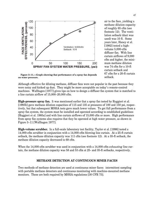
47Figure 3–11.—Graph show<strong>in</strong>g that per<strong>for</strong>mance of a spray fan dependson water pressure.air to the face, yield<strong>in</strong>g amethane dilution capacityof roughly 65 cfm (seefootnote 12). The ventilationsetback (duct wasused) was 10 ft. Someyears later, Haney et al.[1982] tested a highvolume5,000-cfmdiffuser fan. With l<strong>in</strong>ecurta<strong>in</strong> airflows of 9,000cfm and higher, the m<strong>in</strong>imummethane dilutionwas 74 cfm <strong>for</strong> a 10-ftcurta<strong>in</strong> setback and67 cfm <strong>for</strong> a 20-ft curta<strong>in</strong>setback.Although effective <strong>for</strong> dilut<strong>in</strong>g methane, diffuser fans were not popular <strong>in</strong> the past because theywere noisy and kicked up dust. They might be more acceptable on today’s remote-controlmach<strong>in</strong>es. Wallhagen [1977] gives tips on how to design a diffuser fan system that is matched toa l<strong>in</strong>e curta<strong>in</strong> airflow of 15,000–20,000 cfm.High-pressure spray fan. It was mentioned earlier that a spray fan tested by Ruggieri et al.[1985b] gave methane dilution capacities of 115 and 135 at pressures of 100 and 150 psi, respectively,but that subsequent MSHA tests gave much lower values. To get full per<strong>for</strong>mance from aspray fan system, the system must be <strong>in</strong>stalled and operated accord<strong>in</strong>g to established guidel<strong>in</strong>es[Ruggieri et al. 1985a] and with l<strong>in</strong>e curta<strong>in</strong> airflows of 15,000 cfm or more. High per<strong>for</strong>mancefrom spray fan systems also requires that they be operated at high water pressure, as shown <strong>in</strong>Figure 3–11 [Wallhagen 1977].High-volume scrubber. In a full-scale laboratory test facility, Taylor et al. [1996] tested a14,000-cfm scrubber <strong>in</strong> conjunction with a 14,000-cfm blow<strong>in</strong>g l<strong>in</strong>e curta<strong>in</strong>. At a 25-ft curta<strong>in</strong>setback, the methane dilution capacity was 111 cfm (see footnote 12). At a 35-ft setback, themethane dilution capacity decreased to 68 cfm.When the 14,000-cfm scrubber was used <strong>in</strong> conjunction with a 14,000-cfm exhaust<strong>in</strong>g l<strong>in</strong>e curta<strong>in</strong>,the methane dilution capacity was 58 and 53 cfm at 25- and 35-ft setbacks, respectively.METHANE DETECTION AT CONTINUOUS MINER FACESTwo methods of methane detection are used at cont<strong>in</strong>uous m<strong>in</strong>er faces: <strong>in</strong>termittent sampl<strong>in</strong>gwith portable methane detectors and cont<strong>in</strong>uous monitor<strong>in</strong>g with mach<strong>in</strong>e-mounted methanemonitors. These are both required by MSHA regulations [30 CFR 75].
48<strong>Methane</strong> monitors are usually mounted on the side of the cutt<strong>in</strong>g boom of the cont<strong>in</strong>uous m<strong>in</strong>er.The best practice is to select the side that normally sees the highest concentrations. 14 For exhaustventilation systems, <strong>in</strong>clud<strong>in</strong>g spray fan and scrubber systems, this is normally the same side ofthe entry where the exhaust curta<strong>in</strong> (or duct) is located. For blow<strong>in</strong>g ventilation used withscrubber systems, it is normally the opposite side of the entry from the blow<strong>in</strong>g curta<strong>in</strong> (or duct)[Zuchelli et al. 1993; Schultz et al. 1993; Stoltz and Snyder 1991; Snyder et al. 1993; Smith andStoltz 1990; Denk et al. 1988; Snyder et al. 1991; Dupree et al. 1993; Mott and Chuhta 1991;Denk et al. 1989].The required <strong>in</strong>termittent sampl<strong>in</strong>g is a gas check every 20 m<strong>in</strong> with a portable methane detector.A common practice is to attach the portable methane detector to the end of an extensible pole,then to extend the pole out over the cont<strong>in</strong>uous m<strong>in</strong>er as far <strong>for</strong>ward as possible. However, thisis an awkward procedure that requires a long pole, a methane detector with a large readout, andgood eyesight. Another approach, used at deep-cut faces, is to tram out the m<strong>in</strong>er and attach themethane detector to the head us<strong>in</strong>g a magnet. The m<strong>in</strong>er is then trammed back <strong>in</strong> and thedetector read.VENTILATION AND METHANE DETECTION AT BOLTER FACESOn faces that are be<strong>in</strong>g bolted, the l<strong>in</strong>e curta<strong>in</strong> or ventilation duct must always be extended to thelast row of bolts and moved <strong>for</strong>ward when a new row of bolts is <strong>in</strong>stalled. For particularly gassyfaces, it may be necessary to use an extensible curta<strong>in</strong> or duct system [Muldoon et al. 1982].With regard to methane detection, it has always been difficult to make a methane concentrationmeasurement at the face while, at the same time, rema<strong>in</strong><strong>in</strong>g safely under bolted roof. Extendedcutm<strong>in</strong><strong>in</strong>g methods have <strong>in</strong>creased this difficulty because the freshly cut face can extend 40 ft ormore beyond the last row of bolts. To deal with this problem, MSHA has published a new rule[68 Fed. Reg. 15 40132 (2003)]. This new rule, based on the work of Taylor et al. [1999], allowsmethane tests to be made at <strong>in</strong>tervals not exceed<strong>in</strong>g 20 m<strong>in</strong> by sweep<strong>in</strong>g a 16-ft probe <strong>in</strong>by thelast permanently supported roof, provided that a methane monitor is also mounted on the roofbolt<strong>in</strong>gmach<strong>in</strong>e. 16 The methane monitor must be capable of giv<strong>in</strong>g a warn<strong>in</strong>g signal at 1.0%methane and capable of automatically deenergiz<strong>in</strong>g the mach<strong>in</strong>e at 2.0% methane, or if themonitor is not work<strong>in</strong>g properly.Typical ignitions at roof bolter faces have been discussed by Urosek and Francart [1999].REDUCING FRICTIONAL IGNITIONSUp to this po<strong>in</strong>t, the emphasis of this chapter has been solely on ventilation methods andmonitor<strong>in</strong>g <strong>for</strong> gas. However, the chance of a methane ignition may be further reduced by14 For additional <strong>in</strong><strong>for</strong>mation on methane monitor placement, see Chapter 2 on sampl<strong>in</strong>g.15 See Fed. Reg. <strong>in</strong> references.16 See 68 Fed. Reg. 40132 [2003] <strong>for</strong> requirements on methane test<strong>in</strong>g.
- Page 1 and 2: TMIC 9486Information Circular/2006H
- Page 3 and 4: ORDERING INFORMATIONCopies of Natio
- Page 5 and 6: ILLUSTRATIONS—ContinuedPage4-6. U
- Page 8: HANDBOOK FOR METHANE CONTROL IN MIN
- Page 11 and 12: 4Below 5%, called the lower explosi
- Page 13 and 14: 6reduced pressure, except at very l
- Page 15 and 16: 8Static electricity. Protection aga
- Page 17 and 18: 10Figure 1-4.—Estimated methane c
- Page 19 and 20: 12LAYERING OF METHANE AT THE MINE R
- Page 21 and 22: 14good eyesight. 24methane level.Ot
- Page 23 and 24: 16a material balance indicated that
- Page 25 and 26: 18As an example, assume that themet
- Page 27 and 28: 20Figure 1-10.—Relative frequency
- Page 29 and 30: 22Davies AW, Isaac AK, Cook PM [200
- Page 31 and 32: 24Margerson SNA, Robinson H, Wilkin
- Page 33 and 34: CHAPTER 2.—SAMPLING FOR METHANE I
- Page 35 and 36: 29USING PORTABLE METHANE DETECTORST
- Page 37 and 38: Out-of-range gas concentrations in
- Page 39 and 40: Figure 2-3.—Recorder chart from a
- Page 41 and 42: 35Industrial Scientific Corp. [2004
- Page 43 and 44: 38peaks, not the overallmethane lev
- Page 45 and 46: 40hung on J-hook assemblies, which
- Page 47 and 48: 42Methane dilution effectiveness.Th
- Page 49 and 50: 44found that effective scrubber ope
- Page 51: 46When the scrubber exhaust is not
- Page 55 and 56: 50to use radial bits instead of con
- Page 57 and 58: 52Mott ML, Chuhta EJ [1991]. Face v
- Page 59 and 60: 54Service, Centers for Disease Cont
- Page 61 and 62: 56Methane accumulationsaround thesh
- Page 63 and 64: 58corner and by 43% at supportNo. 4
- Page 65 and 66: 60When using water sprays to reduce
- Page 67 and 68: 62Cecala AB, Zimmer JA, Thimons ED
- Page 69 and 70: 64DESIGNING BLEEDER SYSTEMSAs part
- Page 71 and 72: 66Caved area characteristics. The c
- Page 73 and 74: 68then move this gas into the activ
- Page 75 and 76: 70perform tests to determine whethe
- Page 77 and 78: 72A major purpose of the bleeder sy
- Page 79 and 80: 74• Inlets to the pillared area n
- Page 81 and 82: 76REFERENCESCFR. Code of federal re
- Page 83 and 84: 78Methane is released into each min
- Page 85 and 86: 80Figure 6-1.—Gas content of coal
- Page 87 and 88: 82Figure 6-3.—Simplified illustra
- Page 89 and 90: 842. In-mine inclined or vertical b
- Page 91 and 92: 861. Packed cavity method and its v
- Page 93 and 94: 88Table 6-3.—Methane capture rati
- Page 95 and 96: 90Early experiences with this metho
- Page 97 and 98: 9211. At the surface installation (
- Page 99 and 100: 94• Estimated cost for moderately
- Page 101 and 102: 96Thakur PC [1981]. Methane control
- Page 103 and 104:
98Anomalous, unanticipated methane
- Page 105 and 106:
100Vertical methane drainage boreho
- Page 107 and 108:
102Figure 7-2 shows a mine entry ap
- Page 109 and 110:
104obvious solution to this problem
- Page 111 and 112:
106Figure 7-8.—Hypothetical gas c
- Page 113 and 114:
108Lama and Bodziony [1998] compile
- Page 115 and 116:
110In-mine methane drainage systems
- Page 117 and 118:
112Iannacchione AT, Ulery JP, Hyman
- Page 119 and 120:
114More sophisticated reservoir eng
- Page 121 and 122:
116coal lithotype on gas content is
- Page 123 and 124:
118FORECASTING REMAINING GAS-IN-PLA
- Page 125 and 126:
120⎛ y⎞⎜⎛⎞ ⎛ ⎞= ⎜
- Page 127 and 128:
122emissions. The geometry and size
- Page 129 and 130:
124Reservoir models require a subst
- Page 131 and 132:
126King GR, Ertekin T [1989a]. A su
- Page 133 and 134:
128an area of 314 ft 2 would requir
- Page 135 and 136:
130In the case of the abovementione
- Page 137 and 138:
132FILLING SHAFTS AT CLOSED MINESFi
- Page 139 and 140:
134Hinderfeld G [1995]. Ventilation
- Page 141 and 142:
136To calculate the effectiveinert,
- Page 143 and 144:
138exhaust. The remaining diesel ex
- Page 145 and 146:
140required only 4 min. As a result
- Page 147 and 148:
142Figure 11-1.—Desorption test a
- Page 149 and 150:
144enclosed in a tunnel-like struct
- Page 151 and 152:
146Kolada RJ [1985]. Investigation
- Page 153 and 154:
148air in a 6-ft by 9-ft by 6.5-ft
- Page 155 and 156:
150represents flammable mixtures. F
- Page 157 and 158:
152• In Eastern Europe, petroleum
- Page 159 and 160:
154Category II applies to domal sal
- Page 161 and 162:
1562. Monitoring for gas and taking
- Page 163 and 164:
158These mines typically have large
- Page 165 and 166:
160Dave Graham is the safety and he
- Page 167 and 168:
162Figure 13-2.—Examples of metha
- Page 169 and 170:
164REFERENCESAndrews JN [1987]. Nob
- Page 171 and 172:
166APPENDIX A.—ONTARIO OCCUPATION
- Page 174 and 175:
169CHAPTER 14.—PREVENTING METHANE
- Page 176 and 177:
Ways to confirm the presence of gas
- Page 178 and 179:
173The tunnel face is usually venti
- Page 180 and 181:
175Figure 14-5.—TBM ventilation s
- Page 182 and 183:
face. While one of these elements a
- Page 184 and 185:
179ELIMINATING IGNITION SOURCESElec
- Page 186 and 187:
181INDEXAAbnormally gassy faces....
- Page 188 and 189:
183NNatural ventilation, coal silos
- Page 190 and 191:
Delivering on the Nation’s Promis