
You also want an ePaper? Increase the reach of your titles
YUMPU automatically turns print PDFs into web optimized ePapers that Google loves.
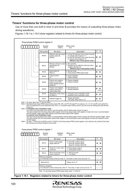
Timers’ functions for three-phase motor controlMitsubishi microcomputers<strong>M16C</strong> / <strong>62</strong> <strong>Group</strong>SINGLE-CHIP 16-BIT CMOS MICROCOMPUTERTimers’ functions for three-phase motor controlUse of more than one built-in timer A and timer B provides the means of outputting three-phase motordriving waveforms.Figures 1.18.1 to 1.18.3 show registers related to timers for three-phase motor control.Three-phase PWM control register 0b7 b6 b5 b4 b3 b2 b1 b0Symbol Address When resetINVC0 034816 0016Bit symbol Bit name Description R WINV00Effective interrupt outputpolarity select bit(Note4)0: A timer B2 interrupt occurs when the timerA1 reload control signal is “1”.1: A timer B2 interrupt occurs when the timerA1 reload control signal is “0”.Effective only in three-phase mode 1INV01INV02Effective interrupt outputspecification bit(Note4)Mode select bit(Note 2)0: Not specified.1: Selected by the effective interrupt outputpolarity selection bit.Effective only in three-phase mode 10: Normal mode1: Three-phase PWM output modeINV03Output controlbit0: Output disabled1: Output enabledINV04INV05INV06INV07Positive and negativephases concurrent Loutput disable functionenable bitPositive and negativephases concurrent Loutput detect flagModulation mode selectbit (Note 3)Software trigger bit0: Feature disabled1: Feature enabled0: Not detected yet1: Already detected0: Triangular wave modulation mode1: Sawtooth wave modulation mode1: Trigger generatedThe value, when read, is “0”.Note 1: No value other than “0” can be written.Note 2: Selecting three-phase PWM output mode causes P80, P81, and P72 through P75 to output U, U, V, V, W, and W, and works thetimer for setting short circuit prevention time, the U, V, W phase output control circuits, and the circuit for setting timer B2 interruptfrequency.Note 3: In triangular wave modulation mode:The short circuit prevention timer starts in synchronization with the falling edge of timer Ai output.The data transfer from the three-phase buffer register to the three-phase output shift register is made only once in synchronizationwith the transfer trigger signal after writing to the three-phase output buffer register.In sawtooth wave modulation mode:The short circuit prevention timer starts in synchronization with the falling edge of timer A output and with the transfer trigger signal.The data transfer from the three-phase output buffer register to the three-phase output shift register is made with respect to everytransfer trigger.Note 4: To write “1” both to bit 0 (INV00) and bit 1 (INV01) of the three-phase PWM control register, set in advance the content of the timerB2 interrupt occurrences frequency set counter.(Note 1)Three-phase PWM control register 1b7 b6 b5 b4 b3 b2 b1 b00Symbol Address When resetINVC1 034916 0016Bit symbolBit nameDescriptionRWINV10Timer Ai start triggersignal select bit0: Timer B2 overflow signal1: Timer B2 overflow signal,signal for writing to timer B2INV11INV12Timer A1-1, A2-1, A4-1control bitShort circuit timer countsource select bit0: Three-phase mode 01: Three-phase mode 10 : Not to be used1 : f1/2 (Note)Noting is assigned.In an attempt to write to this bit, write “0”. The value, if read, turns out to be “0”.Reserved bit Always set to “0”Noting is assigned.In an attempt to write to these bits, write “0”. The value, if read, turns out to be “0”.Note : To use three-phase PWM output mode, write “1” to INV12.Figure 1.18.1. Registers related to timers for three-phase motor control100