
Create successful ePaper yourself
Turn your PDF publications into a flip-book with our unique Google optimized e-Paper software.
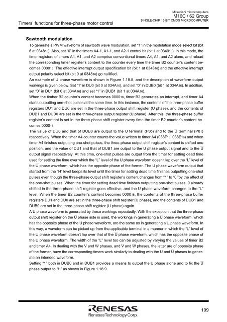
Timers’ functions for three-phase motor controlMitsubishi microcomputers<strong>M16C</strong> / <strong>62</strong> <strong>Group</strong>SINGLE-CHIP 16-BIT CMOS MICROCOMPUTERSawtooth modulationTo generate a PWM waveform of sawtooth wave modulation, set “1” in the modulation mode select bit (bit6 at 034816). Also, set “0” in the timers A4-1, A1-1, and A2-1 control bit (bit 1 at 034916). In this mode, thetimer registers of timers A4, A1, and A2 comprise conventional timers A4, A1, and A2 alone, and reloadthe corresponding timer register’s content to the counter every time the timer B2 counter’s content becomes000016. The effective interrupt output specification bit (bit 1 at 034816) and the effective interruptoutput polarity select bit (bit 0 at 034816) go nullified.An example of U phase waveform is shown in Figure 1.18.8, and the description of waveform outputworkings is given below. Set “1” in DU0 (bit 0 at 034A16), and set “0” in DUB0 (bit 1 at 034A16). In addition,set “0” in DU1 (bit 0 at 034A16) and set “1” in DUB1 (bit 1 at 034A16).When the timber B2 counter’s content becomes 000016, timer B2 generates an interrupt, and timer A4starts outputting one-shot pulses at the same time. In this instance, the contents of the three-phase bufferregisters DU1 and DU0 are set in the three-phase output shift register (U phase), and the contents of___DUB1 and DUB0 are set in the three-phase output register (U phase). After this, the three-phase bufferregister’s content is set in the three-phase shift register every time the timer B2 counter’s content becomes000016.___The value of DU0 and that of DUB0 are output to the U terminal (P80) and to the U terminal (P81)respectively. When the timer A4 counter counts the value written to timer A4 (038F16, 038E16) and whentimer A4 finishes outputting one-shot pulses, the three-phase output shift register’s content is shifted one___position, and the value of DU1 and that of DUB1 are output to the U phase output signal and to the Uoutput signal respectively. At this time, one-shot pulses are output from the timer for setting dead timeused for setting the time over which the “L” level of the U phase waveform doesn’t lap over the “L” level of___the U phase waveform, which has the opposite phase of the former. The U phase waveform output thatstarted from the “H” level keeps its level until the timer for setting dead time finishes outputting one-shotpulses even though the three-phase output shift register’s content changes from “1” to “0 ”by the effect ofthe one-shot pulses. When the timer for setting dead time finishes outputting one-shot pulses, 0 alreadyshifted in the three-phase shift register goes effective, and the U phase waveform changes to the “L”level. When the timer B2 counter’s content becomes 000016, the contents of the three-phase bufferregisters DU1 and DU0 are set in the three-phase shift register (U phase), and the contents of DUB1 and___DUB0 are set in the three-phase shift register (U phase) again.A U phase waveform is generated by these workings repeatedly. With the exception that the three-phase______output shift register on the U phase side is used, the workings in generating a U phase waveform, whichhas the opposite phase of the U phase waveform, are the same as in generating a U phase waveform. Inthis way, a waveform can be picked up from the applicable terminal in a manner in which the “L” level of___the U phase waveform doesn’t lap over that of the U phase waveform, which has the opposite phase ofthe U phase waveform. The width of the “L” level too can be adjusted by varying the values of timer B2___ ___and timer A4. In dealing with the V and W phases, and V and W phases, the latter are of opposite phase___of the former, have the corresponding timers work similarly to dealing with the U and U phases to generatean intended waveform.___Setting “1” both in DUB0 and in DUB1 provides a means to output the U phase alone and to fix the Uphase output to “H” as shown in Figure 1.18.9.109