
You also want an ePaper? Increase the reach of your titles
YUMPU automatically turns print PDFs into web optimized ePapers that Google loves.
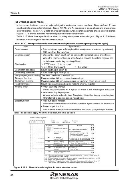
Timer AMitsubishi microcomputers<strong>M16C</strong> / <strong>62</strong> <strong>Group</strong>SINGLE-CHIP 16-BIT CMOS MICROCOMPUTER(2) Event counter modeIn this mode, the timer counts an external signal or an internal timer’s overflow. Timers A0 and A1 cancount a single-phase external signal. Timers A2, A3, and A4 can count a single-phase and a two-phaseexternal signal. Table 1.17.2 lists timer specifications when counting a single-phase external signal.Figure 1.17.8 shows the timer Ai mode register in event counter mode.Table 1.17.3 lists timer specifications when counting a two-phase external signal. Figure 1.17.9 showsthe timer Ai mode register in event counter mode.Table 1.17.2. Timer specifications in event counter mode (when not processing two-phase pulse signal)ItemSpecificationCount source• External signals input to TAiIN pin (effective edge can be selected by software)• TB2 overflow, TAj overflowCount operation• Up count or down count can be selected by external signal or software• When the timer overflows or underflows, it reloads the reload register contents before continuing counting (Note)Divide ratio1/ (FFFF16 - n + 1) for up count1/ (n + 1) for down count n : Set valueCount start condition Count start flag is set (= 1)Count stop condition Count start flag is reset (= 0)Interrupt request generation timing The timer overflows or underflowsTAiIN pin function Programmable I/O port or count source inputTAiOUT pin function Programmable I/O port, pulse output, or up/down count select inputRead from timerCount value can be read out by reading timer Ai registerWrite to timer• When counting stoppedWhen a value is written to timer Ai register, it is written to both reload register and counter• When counting in progressWhen a value is written to timer Ai register, it is written to only reload register(Transferred to counter at next reload time)Select function• Free-run count functionEven when the timer overflows or underflows, the reload register content is not reloaded to it• Pulse output functionEach time the timer overflows or underflows, the TAiOUT pin’s polarity is reversedNote: This does not apply when the free-run function is selected.Timer Ai mode registerb7 b6 b5 b4 b3 b2 b1 b000 1Symbol Address When resetTAiMR(i = 0, 1) 039616, 039716 0016Bit symbol Bit name Function RWWTMOD0 Operation mode select bitb1 b0TMOD10 1 : Event counter mode (Note 1)MR0 Pulse output functionselect bitMR1MR2MR3TCK0TCK1Count polarityselect bit (Note 3)Up/down switchingcause select bit0 : Pulse is not output(TAiOUT pin is a normal port pin)1 : Pulse is output (Note 2)(TAiOUT pin is a pulse output pin)0 (Must always be fixed to “0” in event counter mode)Count operation typeselect bitInvalid in event counter modeCan be “0” or “1”0 : Counts external signal's falling edge1 : Counts external signal's rising edge0 : Up/down flag's content1 : TAiOUT pin's input signal (Note 4)0 : Reload type1 : Free-run typeNote 1: In event counter mode, the count source is selected by the event / trigger select bit(addresses 038216 and 038316).Note 2: The settings of the corresponding port register and port direction register are invalid.Note 3: Valid only when counting an external signal.Note 4: When an “L” signal is input to the TAiOUT pin, the downcount is activated. When “H”,the upcount is activated. Set the corresponding port direction register to “0”.Figure 1.17.8. Timer Ai mode register in event counter mode88