Liebert® IntelliSlot® Modbus 485, Modbus IP and BACnet IP
Liebert® IntelliSlot® Modbus 485, Modbus IP and BACnet IP
Liebert® IntelliSlot® Modbus 485, Modbus IP and BACnet IP

You also want an ePaper? Increase the reach of your titles
YUMPU automatically turns print PDFs into web optimized ePapers that Google loves.
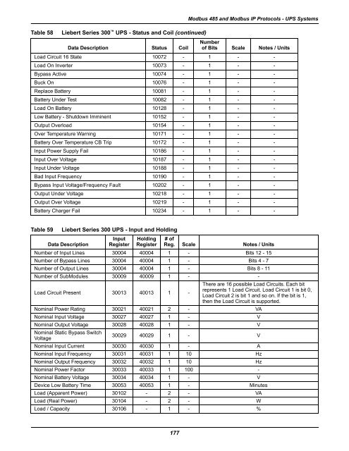
Table 58 Liebert Series 300 UPS - Status <strong>and</strong> Coil (continued)<br />
Data Description Status Coil<br />
177<br />
<strong>Modbus</strong> <strong>485</strong> <strong>and</strong> <strong>Modbus</strong> <strong>IP</strong> Protocols - UPS Systems<br />
Load Circuit 16 State 10072 - 1 - -<br />
Load On Inverter 10073 - 1 - -<br />
Bypass Active 10074 - 1 - -<br />
Buck On 10076 - 1 - -<br />
Replace Battery 10081 - 1 - -<br />
Battery Under Test 10082 - 1 - -<br />
Load On Battery 10128 - 1 - -<br />
Low Battery - Shutdown Imminent 10152 - 1 - -<br />
Output Overload 10154 - 1 - -<br />
Over Temperature Warning 10171 - 1 - -<br />
Battery Over Temperature CB Trip 10172 - 1 - -<br />
Input Power Supply Fail 10186 - 1 - -<br />
Input Over Voltage 10187 - 1 - -<br />
Input Under Voltage 10188 - 1 - -<br />
Bad Input Frequency 10190 - 1 - -<br />
Bypass Input Voltage/Frequency Fault 10202 - 1 - -<br />
Output Under Voltage 10218 - 1 - -<br />
Output Over Voltage 10219 - 1 - -<br />
Battery Charger Fail 10234 - 1 - -<br />
Table 59 Liebert Series 300 UPS - Input <strong>and</strong> Holding<br />
Number<br />
of Bits Scale Notes / Units<br />
Input Holding # of<br />
Data Description Register Register Reg. Scale Notes / Units<br />
Number of Input Lines 30004 40004 1 - Bits 12 - 15<br />
Number of Bypass Lines 30004 40004 1 - Bits 4 - 7<br />
Number of Output Lines 30004 40004 1 - Bits 8 - 11<br />
Number of SubModules 30009 40009 1 - -<br />
Load Circuit Present 30013 40013 1 -<br />
There are 16 possible Load Circuits. Each bit<br />
represents 1 Load Circuit. Load Circuit 1 is bit 0,<br />
Load Circuit 2 is bit 1 <strong>and</strong> so on. If the bit is 1,<br />
then the Load Circuit is supported.<br />
Nominal Power Rating 30021 40021 2 - VA<br />
Nominal Input Voltage 30027 40027 1 - V<br />
Nominal Output Voltage 30028 40028 1 - V<br />
Nominal Static Bypass Switch<br />
Voltage<br />
30029 40029 1 - V<br />
Nominal Input Current 30030 40030 1 - A<br />
Nominal Input Frequency 30031 40031 1 10 Hz<br />
Nominal Output Frequency 30032 40032 1 10 Hz<br />
Nominal Power Factor 30033 40033 1 100 -<br />
Nominal Battery Voltage 30034 40034 1 - V<br />
Device Low Battery Time 30053 40053 1 - Minutes<br />
Load (Apparent Power) 30102 - 2 - VA<br />
Load (Real Power) 30104 - 2 - W<br />
Load / Capacity 30106 - 1 - %