

1938 Cadillac V16 - GM Heritage Center
1938 Cadillac V16 - GM Heritage Center
1938 Cadillac V16 - GM Heritage Center

You also want an ePaper? Increase the reach of your titles
YUMPU automatically turns print PDFs into web optimized ePapers that Google loves.
12<br />
<strong>Cadillac</strong>-LaSalle Preliminary Service Information<br />
With the exception of piston pin removal,<br />
service operations are unchanged from previous<br />
practice. Bearing clearance limits are the same as<br />
for V-8 bearings, and the replacement operations<br />
are the same. Piston fitting is performed in the<br />
same manner and with the same feeler gauges as<br />
used for 37-85 and 90. Cylinder reconditioning is<br />
performed in accordance with the instructions for<br />
the V-8 en-block cylinders. Valve service operations<br />
are the same as for V-8, except that it is<br />
necessary to remove the valves before the valve<br />
lifters can be removed.<br />
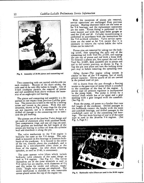
Piston pins are removed by taking out the locking<br />
screw, then spreading the split end of the<br />
connecting rod with Tool No. J-1167, and tapping<br />
the pin out of piston and rod with a brass drift.<br />
To reinstall a piston pin, first spread the rod with<br />
Tool No. J-H67, then assemble pin in piston and<br />
rod in the correct position, as shown in Fig. 8.<br />
Tap the pin into place and turn the locking screw<br />
part way in before removing the spreading tool.<br />
Fig. 8. Assembly of 38-90 piston and connecting rod<br />
Two connecting rods are carried side-by-side on<br />
each crankpin. Because of the short stroke, the<br />
rods need to be only 6% inches in length. Use of<br />
2-inch crankpins permits the removal of piston<br />
and rod assemblies from above without the necessity<br />
of an angle-split rod bearing.<br />
The piston and connecting rod assembly is a departure<br />
in one respect from previous <strong>Cadillac</strong> practice.<br />
The piston pin is held in the rod by a locking<br />
screw and rotates in the piston. With this construction,<br />
shown in Fig. 8, snap rings for the pins<br />
are not required, nor is it necessary to have a<br />
drilled oil passage in the connecting rod to lubricate<br />
the pin bushing.<br />
Thc pistons are of the familiar T-slot design and<br />
are made of aluminum alloy with anodized finish.<br />
Two compression rings and one oil ring are used.<br />
Two grooves are broached the full length of the<br />
piston pin bearing to collect oil from the cylinder<br />
wall and distribute it along the pin.<br />
The valve mechanism in the V-16 engine is<br />
basically the same as the V-8 design. The camshaft<br />
is mounted on five bearings in alternate bulkheads<br />
of the crankcase. It is located in the center<br />
of the vee, directly above the crankshaft, and is<br />
driven by a non-adjustable silent chain at the<br />
front of the engine. An idler chain adjusting<br />
sprocket, as used on 37-90, is unnecessary.<br />
The cams operate valve lifters which include<br />
hydraulic valve silencers of the same design as<br />
used in V-8 engines. (See Fig. 9.) The valves<br />
themselves are of the same materials as used in<br />
V-8 valves but are smaller, with diameters of<br />
and 1¾ inches for intake and exhaust, respectively.<br />
Single valve springs are employed. The<br />
entire mechanism is enclosed by two removable<br />
covers placed across the top of the engine vee.<br />
Oiling System—The engine oiling system is<br />
similar to that of the V-8 engines, but of much<br />
greater capacity. Eleven quarts of oil are carried<br />
in the pressed steel oil pan.<br />
Oil is drawn from the pan through a floating<br />
intake to the gear-type oil pump which is attached<br />
to the crankcase at the rear of the engine. A<br />
piston type oil pressure regulator is incorporated<br />
in the pump body. The pump is driven by a<br />
vertical shaft which has at its upper end a gear<br />
meshing with a gear integral witn the camshaft.<br />
(See Fig. 9).<br />
From the pump, oil passes to a header that runs<br />
full length of the crankcase. Drilled passages in<br />
the bulkheads connect the header with the main<br />
and camshaft bearings, and drilled passages in the<br />
crankshaft carry oil to the connecting rod bearings.<br />
The rear main bearing oil seal is of the same<br />
type as used in the 38-series V-8 engines. (See<br />
Fig. 5, Page 9.)<br />
Fig. 9. Hydraulic valve lifters are used in the 38-90 engine


