

1938 Cadillac V16 - GM Heritage Center
1938 Cadillac V16 - GM Heritage Center
1938 Cadillac V16 - GM Heritage Center

You also want an ePaper? Increase the reach of your titles
YUMPU automatically turns print PDFs into web optimized ePapers that Google loves.
<strong>Cadillac</strong>-LaSalle Preliminary Service Information 15<br />
C<br />
Carburetion and Manifolding.—Gasoline<br />
is drawn forward from the 26 gallon tank through<br />
a single pipe placed in a cool position outside of<br />
the right hand frame sidebar. This pipe branches<br />
near the front of the engine, with one lead passing<br />
directly to the right hand fuel pump and the other<br />
one crossing in front of the frame front crossmember<br />
and then back to the left hand fuel pump.<br />
Heater for<br />
Automatic<br />
Choke<br />
Automatic Choke<br />
Thermostat —<br />
C<br />
The two fuel pumps are of the familiar linkdriven<br />
flexible diaphragm type. The link drives<br />
project inward and engage push rods operated by<br />
eccentrics on the distributor drive shafts, as shown<br />
in Fig. 13. Gasoline filters are an integral part of<br />
the pumps.<br />
A pipe leads from the right hand fuel pump to<br />
the right hand carburetor, and from the left hand<br />
pump to the left hand carburetor, but these lines<br />
are interconnected so that either pump may supply<br />
both carburetors.<br />
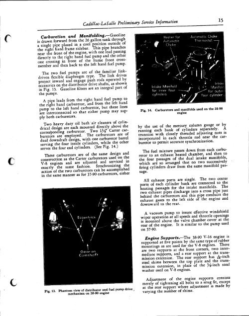
Two heavy duty oil bath "air cleaners of cylindrical<br />
design are each mounted directly above the<br />
corresponding carburetor. Two \Y£ Carter carburetors<br />
are employed. The carburetors are of<br />
dual downdraft design, with one carburetor barrel<br />
serving the four inside cylinders, while the other<br />
serves the four end cylinders. (See Fig. 14.)<br />
These carburetors are of the same design and<br />
construction as the Carter carburetors used on the<br />
V-8 engines and are adjusted and serviced in<br />
exactly the same fashion. Synchronizing the<br />
action of the two carburetors can be accomplished<br />
in the same manner as for 37-90 carburetors, either<br />
Intake Manifold<br />
for inner four<br />
cylinders<br />
» Intake<br />
»" * Manifold<br />
for outer '<br />
four cylinder-,<br />
Fig. 14. Carburetors and manifolds used on the 38-90<br />
engine<br />
by the use of the mercury column gauge or by<br />
running each bank of cylinders separately. A<br />
trunnion with closely threaded adjusting nuts is<br />
incorporated in each throttle rod near the carburetor<br />
to permit accurate synchronization.<br />
The fuel mixture passes down from each carburetor<br />
to an exhaust heated chamber, and then to<br />
the four passages of the dual intake manifolds,<br />
which are so arranged that no two successively<br />
firing cylinders draw from the same manifold passage.<br />
All exhaust ports are single. The two center<br />
Eorts of each cylinder bank are connected to the<br />
eating passages for the intake manifolds. The<br />
two exhaust pipes discharge into a cross pipe just<br />
behind the carburetors and this pipe conducts the<br />
exhaust gases to the left side of the engine and<br />
downward to the rear.<br />
Eccentrics<br />
\ /<br />
Gear on<br />
Camshaft-<br />
^51<br />
A vacuum pump to insure effective windshield<br />
wiper operation at all speeds and throttle openings<br />
is mounted above the valve chamber cover at the<br />
rear of the engine. It is similar to the pump used<br />
on 37-90.<br />
Engine Supports.—The 38-90 V-16 engine is<br />
supported at five points by the same type of rubber<br />
mountings as are used for the V-8 engines. There<br />
are two supports at the front corners, two intermediate<br />
supports, and a rear support at the transmission<br />
extension. The rear support has rV"i 0cn<br />
steel shims between the top plate and the transmission<br />
extension, in place of the )^-inch steel<br />
washer used on V-8 engines.<br />
Fie 13<br />
Phantom view of distributor and fuel pump drive<br />
mechanism on 38-90 engine<br />
Adjustment of the engine supports consists<br />
merely of tightening all bolts to a snug fit, except<br />
at the rear support where adjustment is made by<br />
varying the number of shims.


