

1938 Cadillac V16 - GM Heritage Center
1938 Cadillac V16 - GM Heritage Center
1938 Cadillac V16 - GM Heritage Center

You also want an ePaper? Increase the reach of your titles
YUMPU automatically turns print PDFs into web optimized ePapers that Google loves.
14 <strong>Cadillac</strong>-LaSalle Preliminary Service Information<br />
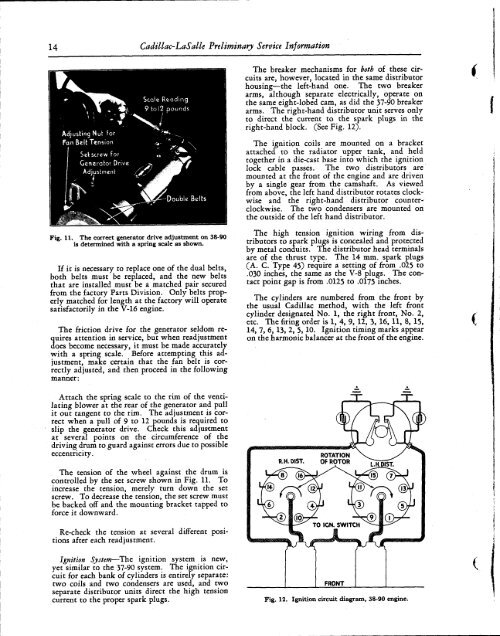
The breaker mechanisms for both of these circuits<br />
are, however, located in the same distributor<br />
housing—the left-hand one. The two breaker<br />
arms, although separate electrically, operate on<br />
the same eight-lobed cam, as did the 37-90 breaker<br />
arms. The right-hand distributor unit serves only<br />
to direct the current to the spark plugs in the<br />
right-hand block. (See Fig. 12).<br />
The ignition coils are mounted on a bracket<br />
attached to the radiator upper tank, and held<br />
together in a die-cast base into which the ignition<br />
lock cable passes. The two distributors are<br />
mounted at the front of the engine and are driven<br />
by a single gear from the camshaft. As viewed<br />
from above, the left hand distributor rotates clockwise<br />
and the right-hand distributor counterclockwise.<br />
The two condensers are mounted on<br />
the outside of the left hand distributor.<br />
Fig. 11. The correct generator drive adjustment on 38-90<br />
is determined with a spring scale as shown.<br />
If it is necessary to replace one of the dual belts,<br />
both belts must be replaced, and the new belts<br />
that are installed must be a matched pair secured<br />
from the factory Parts Division. Only belts properly<br />
matched for length at the factory will operate<br />
satisfactorily in the V-16 engine.<br />
The friction drive for the generator seldom reuires<br />
attention in service, but when readjustment<br />
3oes become necessary, it must be made accurately<br />
with a spring scale. Before attempting this adjustment,<br />
make certain that the fan belt is correctly<br />
adjusted, and then proceed in the following<br />
manner:<br />
The high tension ignition wiring from distributors<br />
to spark plugs is concealed and protected<br />
by metal conduits. The distributor head terminals<br />
are of the thrust type. The 14 mm. spark plugs<br />
(A. C. Type 45) require a setting of from .025 to<br />
.030 inches, the same as the V-8 plugs. The contact<br />
point gap is from .0125 to .0175 inches.<br />
The cylinders are numbered from the front by<br />
the usual <strong>Cadillac</strong> method, with the left front<br />
cylinder designated No. 1, the right front, No. 2,<br />
etc. The firing order is 1, 4, 9, 12, 3, 16, 11, 8, 15,<br />
14, 7, 6,13, 2, 5,10. Ignition timing marks appear<br />
on the harmonic balancer at the front of the engine.<br />
Attach the spring scale to the rim of the ventilating<br />
blower at the rear of the generator and pull<br />
it out tangent to the rim. The adjustment is correct<br />
when a pull of 9 to 12 pounds is required to<br />
slip the generator drive. Check this adjustment<br />
at several points on the circumference of the<br />
driving drum to guard against errors due to possible<br />
eccentricity.<br />
The tension of the wheel against the drum is<br />
controlled by the set screw shown in Fig. 11. To<br />
increase the tension, merely turn down the set<br />
screw. To decrease the tension, the set screw must<br />
be backed off and the mounting bracket tapped to<br />
force it downward.<br />
Re-check the tension at several different positions<br />
after each readjustment.<br />
Ignition System—The ignition system is new,<br />
yet similar to the 37-90 system. The ignition circuit<br />
for each bank of cylinders is entirely separate:<br />
two coils and two condensers are used, and two<br />
separate distributor units direct the high tension<br />
current to the proper spark plugs.<br />
FRONT<br />
Fig. 12. Ignition circuit diagram, 38-90 engine.


