- Page 2 and 3:
Proceedings of the 5th Cross-strait
- Page 4 and 5:
SCIENTIFIC COMMITTEE Chairman Jan-M
- Page 6 and 7:
ORGANIZING COMMITTEE Co-chairmen Yi
- Page 8 and 9:
设 计 大 师 金 问 鲁 教 授
- Page 10 and 11:
TABLE OF CONTENTS Scientific Commit
- Page 12 and 13:
J.T. Shi & L. Su Impact of Spatial
- Page 14 and 15:
Temperature Effect on Variation of
- Page 16 and 17:
Trace Analysis of Mechanical Respon
- Page 18 and 19:
Keynote Lectures
- Page 20 and 21:
图 1 海 峡 大 桥 三 个 路
- Page 22 and 23:
非 主 通 航 孔 的 跨 径 应
- Page 24 and 25:
The 5th Cross-strait Conference on
- Page 26 and 27:
图 3 空 间 结 构 按 单 元
- Page 28 and 29:
图 7 多 面 体 空 间 框 架
- Page 30 and 31:
图 14 内 蒙 古 响 沙 湾 沙
- Page 32 and 33:
5.3. MRF3 索 穹 顶 — 网 壳
- Page 34 and 35:
图 29 杭 州 黄 龙 体 育 中
- Page 36 and 37:
(a) 鸟 瞰 图 (b) 计 算 模 型
- Page 38 and 39:
The 5th Cross-strait Conference on
- Page 40 and 41:
As it is conventional, the displace
- Page 42 and 43:
⎡ n n ⎤ ⎢q 1 0( z− Li) q0(
- Page 44 and 45:
frequencies of interest and the tra
- Page 46 and 47:
Another phenomenon observed from Fi
- Page 48 and 49:
The 5th Cross-strait Conference on
- Page 50 and 51:
刚 塑 性 平 面 应 变 极 限
- Page 52 and 53:
采 用 数 值 极 限 分 析 法
- Page 54 and 55:
为 了 推 测 浅 埋 隧 洞 破
- Page 56 and 57:
鹤 梁 岩 壁 面 上 至 今 已
- Page 58 and 59:
图 6 黄 庭 坚 题 铭 “ 元
- Page 60 and 61:
图 16 巫 山 神 女 图 17 长
- Page 62 and 63:
五 、 历 年 来 研 究 过 的
- Page 64 and 65:
在 会 议 结 束 前 给 我 半
- Page 66 and 67:
图 31 院 士 建 议 文 件 的
- Page 68 and 69:
科 所 、 重 庆 交 通 学 院
- Page 70 and 71:
图 37 白 鹤 梁 题 刻 中 段
- Page 72 and 73:
图 46 上 下 游 水 平 交 通
- Page 74 and 75:
图 59 参 观 廊 道 安 装 在
- Page 76 and 77:
9.6. 白 鹤 梁 水 下 博 物
- Page 78 and 79:
(5) “ 无 压 容 器 ” 水 下
- Page 80 and 81:
-62-
- Page 82 and 83:
-64-
- Page 84 and 85:
-66-
- Page 86 and 87:
-68-
- Page 88 and 89:
The 5th Cross-strait Conference on
- Page 90 and 91:
(a) 模 型 I (b) 模 型 II (c)
- Page 92 and 93:
(a) 水 平 接 缝 处 螺 钉 松
- Page 94 and 95:
表 5 模 型 I 在 9 度 罕 遇
- Page 96 and 97:
The 5th Cross-strait Conference on
- Page 98 and 99:
1.2. 大 型 钢 结 构 设 计
- Page 100 and 101:
5250 5000 i= 0.07 1 i= 0.07 5000 16
- Page 102 and 103:
A Pb Pa Pb A Pb Pa Pb Pa Pa ax Pb P
- Page 104 and 105:
(a) 预 应 力 索 布 置 (b) 1/6
- Page 106 and 107:
图 23 150m×150m 周 边 简 支
- Page 108 and 109:
图 27(a) 自 重 作 用 下 结
- Page 110:
四 、 结 语 150m×150m 空 间
- Page 113 and 114:
The 5th Cross-strait Conference on
- Page 115 and 116:
通 过 上 述 技 术 创 新 平
- Page 117 and 118:
The 5th Cross-strait Conference on
- Page 119 and 120:
* θt r1cosθ r2cosθ2 = = (9) * 1
- Page 121 and 122:
圖 10 水 平 軌 枕 方 向 之
- Page 123 and 124:
圖 19 水 平 軌 枕 方 向 之
- Page 125 and 126:
向 量 r r &r r 的 變 化 率
- Page 127 and 128:
Experimental Program More than 60 l
- Page 129 and 130:
failure mode specimens, applying CF
- Page 131 and 132:
columns were reinforced with three
- Page 133 and 134:
e formed at the column base and the
- Page 135 and 136:
Acceleration (g) 1 0.5 0 -0.5 Simul
- Page 137 and 138:
The 5th Cross-strait Conference on
- Page 139 and 140:
Table 2 Mix Proportion of the PDCC
- Page 141 and 142:
observed between the formwork and c
- Page 143 and 144:
In the above example, the GFRP with
- Page 145 and 146:
构 的 加 固 修 复 , 二 是
- Page 147 and 148:
FRP 网 格 FRP 筋 和 索 FRP 布
- Page 149 and 150:
(2) 钢 筋 - 连 续 纤 维 复
- Page 151 and 152:
生 退 化 。 拉 伸 强 度 相
- Page 153 and 154:
图 16 两 种 纤 维 混 杂 增
- Page 155 and 156:
σ tf 混 凝 土 构 件 粘 结
- Page 157 and 158:
新 型 抗 震 结 构 的 荷 载
- Page 159 and 160:
的 破 坏 过 程 也 与 柱 C-S
- Page 161 and 162:
拉 索 频 率 阶 数 也 低 于
- Page 163 and 164:
A m plitude (m m ) 6000 5000 4000 3
- Page 165 and 166:
产 工 艺 进 行 探 索 性 研
- Page 167 and 168:
Girders with Externally Prestressed
- Page 169 and 170:
concrete columns were documented by
- Page 171 and 172:
fatigue life of steel columns. Xiao
- Page 173 and 174:
Figure 11 Relationships between res
- Page 175 and 176:
20. Xiao, Y. and Wu, H. (2000). “
- Page 177 and 178:
phenomenon, however, cannot be cons
- Page 179 and 180:
ase rock; H j ( iω) , H k ( iω) a
- Page 181 and 182:
For the coherency loss function bet
- Page 183 and 184:
Numerical Results The earthquake-in
- Page 185 and 186:
REFERENCES Bi, K., Hao, H. and Ren,
- Page 187 and 188:
The 5th Cross-strait Conference on
- Page 189 and 190:
Figure 3 Idealised bonded joint mod
- Page 191 and 192:
A = 0 1 (6a) B1 = −δ f (6b) f si
- Page 193 and 194:
Table 1 Test and predicted flexural
- Page 195 and 196:
COMPARISON OF FLEXURAL DEBONDING MO
- Page 197 and 198:
The 5th Cross-strait Conference on
- Page 199 and 200:
Figure 2 Location of smart aggregat
- Page 201 and 202:
Figure 5 Experimental setup Figure
- Page 203 and 204:
Figure 15 Impact location on FRP wr
- Page 205 and 206:
REFERENCES Bhalla, S. and Soh, C.K.
- Page 207 and 208:
The 5th Cross-strait Conference on
- Page 209 and 210:
The RVE, occupying a geometrical do
- Page 211 and 212:
[ ut ] is the tangential vector if
- Page 213 and 214:
extended to the resolution of the n
- Page 215 and 216:
469.1m,f m =55%,f I =45% -50 Σ 3 -
- Page 217 and 218:
The 5th Cross-strait Conference on
- Page 219 and 220:
頭 混 凝 土 護 蓋 敲 除 ,
- Page 221 and 222:
發 生 夾 片 咬 合 失 敗 ,
- Page 223 and 224:
會 因 設 計 長 度 不 足 ,
- Page 225 and 226:
面 之 反 推 分 析 可 知 ,
- Page 227 and 228:
因 此 連 擋 土 牆 本 身 之
- Page 229 and 230:
⎛τ ⎞ av ⎛amax ⎞⎛σ ⎞ v
- Page 231 and 232:
地 液 化 与 否 初 步 判 别
- Page 233 and 234:
等 (2000) [15] 在 试 验 中 都
- Page 235 and 236:
五 、 结 论 剪 切 波 速 法
- Page 237 and 238:
The 5th Cross-strait Conference on
- Page 239 and 240:
钢 混 凝 土 相 当 于 将 型
- Page 241 and 242:
A g — 混 凝 土 毛 截 面 面
- Page 243 and 244:
5.1. 大 连 市 体 育 馆 钢
- Page 245 and 246:
土 梁 中 设 立 直 线 预 应
- Page 247 and 248:
The 5th Cross-strait Conference on
- Page 249 and 250:
混 凝 土 板 外 侧 , 受 力
- Page 251 and 252:
试 验 采 用 跨 中 两 点 对
- Page 253 and 254:
为 了 深 入 了 解 槽 型 钢
- Page 255 and 256:
笔 者 针 对 已 有 结 合 部
- Page 257 and 258:
面 , 浇 注 的 混 凝 土 和
- Page 259 and 260:
(c) 波 形 钢 腹 板 工 字 型
- Page 261 and 262:
The 5th Cross-strait Conference on
- Page 263 and 264:
The 5th Cross-strait Conference on
- Page 265 and 266:
manner for statistical analysis, (i
- Page 267 and 268:
3.3.1 Software System for Instrumen
- Page 269 and 270:
spectrum is obtained in an approxim
- Page 271 and 272:
e carried out once per maintenance
- Page 273 and 274:
The monitoring work is composed of
- Page 275 and 276:
displacement influence lines and st
- Page 277 and 278:
efers to data processing and storag
- Page 279 and 280:
Hong Kong Institution of Engineers.
- Page 281 and 282:
Monitoring Category Bridge Features
- Page 283 and 284:
9 Combination of Above Divided Sect
- Page 285 and 286:
Back to Routine Monitoring Not Exce
- Page 287 and 288:
Tsing Yi Stonecutters Figure 5 Layo
- Page 289 and 290:
Continuous Data Acquisition GPS Tim
- Page 291 and 292:
Y(+ve) Y T Temperature Distribution
- Page 293 and 294:
Type of Input Data Type of Data Pro
- Page 295 and 296:
Type of Input Data Type of Data Pro
- Page 297 and 298:
Type of Input Data Type of Data Pro
- Page 299 and 300:
Type of Input Data Type of Data Pro
- Page 301 and 302:
Tsing Yi Stonecutters Stonecutters
- Page 303 and 304:
青 衣 Tsing Yi 昂 船 洲 Stonec
- Page 305 and 306:
Accelerometer Fixing of Portable Ac
- Page 307 and 308:
Tsing Yi Stonecutters Bridge Stonec
- Page 309 and 310:
Structural Health Data Management S
- Page 311 and 312:
a mean recurrence interval with ext
- Page 313 and 314:
The present study is concerned with
- Page 315 and 316:
which all the variables have the sa
- Page 317 and 318:
450 35 400 30 350 300 25 ( 1.0E- 6)
- Page 319 and 320:
Structural Engineering and Mechanic
- Page 321 and 322:
The 5th Cross-strait Conference on
- Page 323 and 324:
provided in DBELA, a base rotation
- Page 325 and 326:
ξ ( μ − ) 3 eq −ξ0 = C + D 1
- Page 327 and 328:
equivalent displacements exceed the
- Page 329 and 330:
Displacement (cm) 70 60 50 40 30 20
- Page 331 and 332:
it give rather reasonable results,
- Page 333 and 334:
RANDOM FIELD AND SPATIAL AVERAGING
- Page 335 and 336:
satisfactorily when SOF is large bu
- Page 337 and 338:
those of the average shear strength
- Page 339 and 340:
then rinsed three times with deioni
- Page 341 and 342:
The Freundlich model can be express
- Page 343 and 344:
Ministry of Education for their fin
- Page 345 and 346:
United States.) The available site
- Page 347 and 348:
ACKNOWLEDGMENTS Financial support f
- Page 349 and 350:
the author has quoted the outdated
- Page 351 and 352:
Figure 5 The geological map of 2000
- Page 353 and 354:
Figure 11 Rock cores of vent brecci
- Page 355 and 356:
Due to the misidentification of roc
- Page 357 and 358:
ACKNOWLEDGEMENT The author would of
- Page 359 and 360:
Recently, as the development of fin
- Page 361 and 362:
( x ) ( x ) L m ( x ) ( x ) ( x ) L
- Page 363 and 364:
Step1: initializing the nonlinear o
- Page 365 and 366:
Table 1 The results of limit load m
- Page 367 and 368:
Khosravifard, A., Hematiyan, M.R. (
- Page 369 and 370:
阿 坝 州 没 有 水 库 , 凉
- Page 371 and 372:
汶 川 地 震 中 属 于 溃 坝
- Page 373 and 374:
缝 宽 约 2mm~5mm; 纵 向 断
- Page 375 and 376:
The 5th Cross-strait Conference on
- Page 377 and 378:
Problem with Seismic Hazard Analysi
- Page 379 and 380: INADEQUACY OF TSUNAMI MITIGATION ST
- Page 381 and 382: demonstrated that huge earthquake c
- Page 383 and 384: The 5th Cross-strait Conference on
- Page 385 and 386: 三 、 粮 库 室 内 地 面 沉
- Page 387 and 388: 土 层 的 物 理 力 学 参 数
- Page 389 and 390: 笔 者 对 4# 粮 库 的 沉 降
- Page 391 and 392: 二 国 标 中 主 动 土 压 力
- Page 393 and 394: 表 3 c =0kPa 时 不 同 的 δ
- Page 395 and 396: 的 值 比 公 式 (1) 的 值 小
- Page 397 and 398: [1] 究 等 方 面 都 有 了 新
- Page 399 and 400: (3) 根 据 对 隧 道 典 型 断
- Page 401 and 402: 水 平 收 敛 位 移 (mm) 12.00
- Page 403 and 404: The 5th Cross-strait Conference on
- Page 405 and 406: THREE PROCEDURES FOR SCALING GROUND
- Page 407 and 408: Peak displacement (m) 84, 50, 16 pe
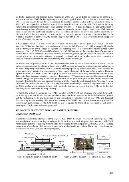
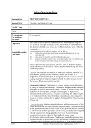
- Page 409 and 410: CONCLUSIONS Performance-based desig
- Page 411 and 412: The 5th Cross-strait Conference on
- Page 413 and 414: Figure 3 Physical diagrams of pile
- Page 415 and 416: load-deflection curve at the pile h
- Page 417 and 418: 在 此 选 取 Kondner [10] 及 Go
- Page 419 and 420: 及 附 加 内 力 的 简 单 方
- Page 421 and 422: The 5th Cross-strait Conference on
- Page 423 and 424: The dual is min * w, b, ξξ , s.t
- Page 425 and 426: Table 1 The results of example 1 Re
- Page 427 and 428: P P P P P P P P P P P P 4 5 4 A 2 4
- Page 429: The 5th Cross-strait Conference on
- Page 433 and 434: SHAKING TABLE TEST PROGRAM System i
- Page 435 and 436: Force (N) 600 500 400 300 200 100 N
- Page 437 and 438: Figure 9 Comparison of SAF-TMD and
- Page 439 and 440: The 5th Cross-strait Conference on
- Page 441 and 442: 鋼 線 , 近 期 更 發 展 為
- Page 443 and 444: 三 、 吊 橋 基 本 資 料 表
- Page 445 and 446: 底 端 固 定 型 式 □ 夾 具
- Page 447 and 448: 4.2.3 吊 橋 扭 轉 行 為 之
- Page 449 and 450: The 5th Cross-strait Conference on
- Page 451 and 452: 由 式 (11)~(13) 可 求 得 闭
- Page 453 and 454: 3.2 脉 动 风 压 时 程 结 构
- Page 455 and 456: 4.2 主 动 控 制 力 分 析 图
- Page 457 and 458: The 5th Cross-strait Conference on
- Page 459 and 460: egarded as a serviceability limit s
- Page 461 and 462: observed that the measured values c
- Page 463 and 464: _ Cumulative Frequency of Samples (
- Page 465 and 466: 三 个 项 目 基 本 概 况 对
- Page 467 and 468: 风 作 用 下 基 底 总 X 向 7
- Page 469 and 470: 主 要 技 术 指 标 对 比 表
- Page 471 and 472: 六 、 上 部 结 构 材 料 用
- Page 473 and 474: m 2 , 三 个 项 目 采 用 混
- Page 475 and 476: STADIUM ROOF BRIEF Jaber Al-Ahmad I
- Page 477 and 478: a) 1st modal shape Figure.7 Modal s
- Page 479 and 480: The 5th Cross-strait Conference on
- Page 481 and 482:
1) 所 需 的 机 具 设 备 少
- Page 483 and 484:
6.1. 挠 度 选 取 典 型 加
- Page 485 and 486:
七 、 结 论 通 过 上 述 研
- Page 487 and 488:
where c = cope length,D = beam dept
- Page 489 and 490:
A post-ultimate stiffness of 200 MP
- Page 491 and 492:
Table 3 Summary of the variables of
- Page 493 and 494:
Effects of Web Slenderness (d/t w )
- Page 495 and 496:
REFERENCES ABAQUS/Standard User’s
- Page 497 and 498:
规 程 [7]。 文 献 [2]、[3]
- Page 499 and 500:
为 探 究 球 节 点 壁 厚 对
- Page 501 and 502:
[4] 王 星 , 董 石 麟 , 完 海
- Page 503 and 504:
一 、 前 言 鋼 纜 為 斜 張
- Page 505 and 506:
圖 1 愛 蘭 矮 塔 斜 張 橋
- Page 507 and 508:
態 頻 率 後 , 由 圖 6 可 清
- Page 509 and 510:
素 連 接 , 假 設 兩 構 件
- Page 511 and 512:
The 5th Cross-strait Conference on
- Page 513 and 514:
图 3 半 片 梁 的 有 限 元
- Page 515 and 516:
加 固 前 的 钢 筋 混 凝 土
- Page 517 and 518:
The 5th Cross-strait Conference on
- Page 519 and 520:
and a corresponding shear strain of
- Page 521 and 522:
The 5th Cross-strait Conference on
- Page 523 and 524:
对 温 度 变 化 效 应 进 行
- Page 525 and 526:
典 型 节 点 : 在 钢 结 构
- Page 527 and 528:
钢 结 构 第 一 阶 振 型 为
- Page 529 and 530:
(a) 上 支 座 节 点 (b) 下 支
- Page 531 and 532:
上 部 屋 面 钢 结 构 下 部
- Page 533 and 534:
验 算 4、6 号 线 重 力 荷
- Page 535 and 536:
采 用 SAP2000, 对 各 种 截
- Page 537 and 538:
The 5th Cross-strait Conference on
- Page 539 and 540:
高 屏 溪 引 橋 共 包 含 五
- Page 541 and 542:
表 3 由 高 屏 溪 斜 張 橋
- Page 543 and 544:
圖 7 垂 直 撓 曲 第 一 振
- Page 545 and 546:
表 7 在 P2 橋 墩 不 同 沖