- Page 1 and 2:
KIRTLAND AIR FORCE BASE ALBUQUERQUE
- Page 3 and 4:
DOCUMENT CERTIFICATION REPORT DOCUM
- Page 5 and 6:
DOCUMENT CERTIFICATION THIS PAGE IN
- Page 7 and 8:
CONTENTS 3.3.7 Groundwater and LNAP
- Page 9 and 10:
FIGURES FIGURES 2-1 Site Location M
- Page 11 and 12:
ACRONYMS AND ABBREVIATIONS ACRONYMS
- Page 13 and 14:
THIS PAGE INTENTIONALLY LEFT BLANK
- Page 15 and 16:
SECTION 1 1.1 Objectives and Scope
- Page 17 and 18:
SECTION 2 2.1 Site Description 2. B
- Page 19 and 20:
SECTION 2 • From roughly 86 ft bg
- Page 21 and 22:
SECTION 2 2.4.2 Investigative Resul
- Page 23 and 24:
SECTION 2 previous sampling results
- Page 25 and 26:
SECTION 2 the soils. Only that part
- Page 27 and 28:
SECTION 2 gpd. Investigating and re
- Page 29 and 30:
SECTION 3 3.2 Quality Assurance/Qua
- Page 31 and 32:
SECTION 3 being both an electrical
- Page 33 and 34:
SECTION 3 3.3.4 Groundwater Monitor
- Page 35 and 36:
SECTION 3 piezometers. Groundwater
- Page 37 and 38:
SECTION 4 association meetings are
- Page 39 and 40:
REFERENCES US Environmental Protect
- Page 41 and 42:
TABLES Table 2-1. Hydrostratigraphi
- Page 43 and 44:
TABLES Table 3-2 Proposed Installat
- Page 45 and 46:
TABLES Installation ID Installation
- Page 47 and 48:
TABLES Installation ID Installation
- Page 49 and 50:
TABLES Installation ID Installation
- Page 51 and 52:
Figures
- Page 53 and 54:
SAN METEO SAN PEDRO 1540886 1541386
- Page 55 and 56:
Source: CH2M HILL 2009 Figure 2-4
- Page 57 and 58:
Source: CH2M HILL 2009 Figure 2-6
- Page 59 and 60:
CONCEPTUAL SITE MODEL Figure 2-8 So
- Page 61 and 62:
SAN METEO SAN PEDRO 1540672 1541172
- Page 63 and 64:
Figure 3‐3 Typical Soil Vapor Mon
- Page 65 and 66:
Appendix A NMED Guidance: NMED TPH
- Page 67 and 68:
A TPH screening guideline was calcu
- Page 69 and 70:
potential indoor air impacts from s
- Page 71 and 72:
Appendix B Project Schedule
- Page 73 and 74:
Appendix C Preliminary Report Outli
- Page 75 and 76:
Appendix D Base-Wide Plans for Inve
- Page 78 and 79:
BASE-WIDE PLAN CONTENTS Section Pag
- Page 80 and 81:
BASE-WIDE PLAN FIGURES Section Page
- Page 82 and 83:
BASE-WIDE PLAN ACRONYMS AFB AFCEE C
- Page 84 and 85:
BASE-WIDE PLAN 1. INTRODUCTION Kirt
- Page 86 and 87:
BASE-WIDE PLAN 2. PROJECT MANAGEMEN
- Page 88 and 89:
BASE-WIDE PLAN Waste Management Pro
- Page 90 and 91:
BASE-WIDE PLAN 3. BASELINE ENVIRONM
- Page 92 and 93:
BASE-WIDE PLAN Figure 3-1. Kirtland
- Page 94 and 95:
BASE-WIDE PLAN Table 3-1. History o
- Page 96 and 97:
BASE-WIDE PLAN Figure 3-2. Location
- Page 98 and 99:
BASE-WIDE PLAN Figure 3-3. Geologic
- Page 100 and 101:
BASE-WIDE PLAN 3.1.3 Hydrogeology D
- Page 102 and 103:
BASE-WIDE PLAN the high nitrate lev
- Page 104 and 105:
BASE-WIDE PLAN Figure 3-4. Extent o
- Page 106 and 107:
BASE-WIDE PLAN REFERENCES Allen, H.
- Page 108 and 109:
APPENDIX A APPENDIX A Field Samplin
- Page 110 and 111:
APPENDIX A CONTENTS Section Page Ta
- Page 112 and 113:
APPENDIX A TABLES Table Page Table
- Page 114 and 115:
APPENDIX A ACRONYMS °C degrees Cel
- Page 116 and 117:
APPENDIX A 1. INTRODUCTION This Bas
- Page 118 and 119:
APPENDIX A 2. FIELD SAMPLING OBJECT
- Page 120 and 121:
APPENDIX A 3. DESIGN OF DATA COLLEC
- Page 122 and 123:
APPENDIX A Table 3-1. Activities As
- Page 124 and 125: APPENDIX A probability. This techni
- Page 126 and 127: APPENDIX A 4. SAMPLING EQUIPMENT AN
- Page 128 and 129: APPENDIX A 4.3.3 Ambient Field Blan
- Page 130 and 131: APPENDIX A 5. SAMPLE HANDLING AND A
- Page 132 and 133: APPENDIX A 6. FIELD QA/QC PROGRAM T
- Page 134 and 135: APPENDIX A 7. SITE MANAGEMENT AND R
- Page 136 and 137: APPENDIX A The identity of each sam
- Page 138 and 139: APPENDIX A REFERENCES EPA 1986. RCR
- Page 140 and 141: APPENDIX B APPENDIX B Standard Oper
- Page 142 and 143: APPENDIX B CONTENTS Section Page Ta
- Page 144 and 145: APPENDIX B CONTENTS (Continued) Sec
- Page 146 and 147: APPENDIX B TABLES Table B4.1-1. Qui
- Page 148 and 149: APPENDIX B FIGURES Figure B1.1-1. T
- Page 150 and 151: APPENDIX B ACRONYMS °C degrees Cel
- Page 152 and 153: APPENDIX B SOP B1.1 Borehole and Sa
- Page 154 and 155: APPENDIX B Gravely soils are identi
- Page 156 and 157: APPENDIX B Stratification Stratific
- Page 158 and 159: APPENDIX B Hardness The hardness of
- Page 160 and 161: APPENDIX B Igneous rock classificat
- Page 162 and 163: APPENDIX B Figure B1.1-1. Typical B
- Page 164 and 165: APPENDIX B Figure B1.1-1. Typical B
- Page 166 and 167: APPENDIX B Figure B1.1-2. The Unifi
- Page 168 and 169: APPENDIX B SOP B1.2 Borehole Geophy
- Page 170 and 171: APPENDIX B Waveforms obtained at ea
- Page 172 and 173: APPENDIX B The borehole induction s
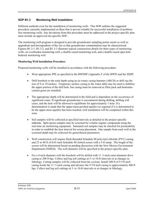
- Page 176 and 177: APPENDIX B finished wells shall als
- Page 178 and 179: APPENDIX B Figure B1.3-1. Overburde
- Page 180 and 181: APPENDIX B Figure B1.3-2. Overburde
- Page 182 and 183: APPENDIX B Figure B1.3-3. Double Ca
- Page 184 and 185: APPENDIX B Figure B1.3-4. Double Ca
- Page 186 and 187: APPENDIX B SOP B1.4 Monitoring Well
- Page 188 and 189: APPENDIX B Chemical application The
- Page 190 and 191: APPENDIX B Figure B1.4-1. Well Deve
- Page 192 and 193: APPENDIX B Figure B1.4-1. Well Deve
- Page 194 and 195: APPENDIX B SOP B1.5 Monitoring Well
- Page 196 and 197: APPENDIX B Figure B1.5-1. Well Aban
- Page 198 and 199: APPENDIX B SOP B1.6 Temporary Well-
- Page 200 and 201: APPENDIX B SOP B1.7 Soil Gas Invest
- Page 202 and 203: APPENDIX B If instrument blanks ind
- Page 204 and 205: APPENDIX B SOP B1.8 Surficial Geoph
- Page 206 and 207: APPENDIX B Relevant notes, remarks
- Page 208 and 209: APPENDIX B Magnetic Surveys useful
- Page 210 and 211: APPENDIX B SOP B1.9 Land Surveys A
- Page 212 and 213: APPENDIX B SOP B1.10 Meteorological
- Page 214 and 215: APPENDIX B SOP B1.11 Equipment Deco
- Page 216 and 217: APPENDIX B Personal Protective Equi
- Page 218 and 219: APPENDIX B SOP B2.1 Sediment Sampli
- Page 220 and 221: APPENDIX B SOP B2.2 Surface Soil Sa
- Page 222 and 223: APPENDIX B SOP B2.3 Subsurface Soil
- Page 224 and 225:
APPENDIX B Wear appropriate PPE as
- Page 226 and 227:
APPENDIX B the Classification of Ro
- Page 228 and 229:
APPENDIX B Using soil removed from
- Page 230 and 231:
APPENDIX B Collect and manage all w
- Page 232 and 233:
APPENDIX B SOP B2.4 Test Pit Sampli
- Page 234 and 235:
APPENDIX B SOP B2.5 Sample Homogeni
- Page 236 and 237:
APPENDIX B SOP B3.1 Photoionization
- Page 238 and 239:
APPENDIX B SOP B3.2 Methods for Usi
- Page 240 and 241:
APPENDIX B The rate of migration th
- Page 242 and 243:
APPENDIX B easily be penetrated wit
- Page 244 and 245:
APPENDIX B the identification or qu
- Page 246 and 247:
APPENDIX B SOP B3.3 Headspace Scree
- Page 248 and 249:
APPENDIX B SOP B4.1 Monitoring Well
- Page 250 and 251:
APPENDIX B the drawdown shall not e
- Page 252 and 253:
APPENDIX B Sample Collection Once r
- Page 254 and 255:
APPENDIX B Figure B4.1-1. Well Purg
- Page 256 and 257:
APPENDIX B Table B4.1-1. Quick Conv
- Page 258 and 259:
APPENDIX B SOP B4.2 Potable Water S
- Page 260 and 261:
APPENDIX B SOP B4.3 Surface Water S
- Page 262 and 263:
APPENDIX B SOP B4.4 Field Filtratio
- Page 264 and 265:
APPENDIX B SOP B5.1 pH The followin
- Page 266 and 267:
APPENDIX B SOP B5.2 Specific Conduc
- Page 268 and 269:
APPENDIX B SOP B5.3 Water Temperatu
- Page 270 and 271:
APPENDIX B SOP B5.4 Dissolved Oxyge
- Page 272 and 273:
APPENDIX B SOP B5.5 Oxidation-Reduc
- Page 274 and 275:
APPENDIX B SOP B5.6 Water Levels Wa
- Page 276 and 277:
APPENDIX B Figure B5.6-1. Groundwat
- Page 278 and 279:
APPENDIX B SOP B5.7 Aquifer Testing
- Page 280 and 281:
APPENDIX B Packer Testing Procedure
- Page 282 and 283:
APPENDIX B All measurements and obs
- Page 284 and 285:
APPENDIX B Figure B5.7-1a. Aquifer
- Page 286 and 287:
APPENDIX B Figure B5.7-1b. Aquifer
- Page 288 and 289:
APPENDIX B Figure B5.7-2. Pump Test
- Page 290 and 291:
APPENDIX B SOP B6.1 Drum Sampling F
- Page 292 and 293:
APPENDIX B SOP B6.2 Tank Sampling F
- Page 294 and 295:
APPENDIX B SOP B6.3 Wipe Sampling T
- Page 296 and 297:
APPENDIX B SOP B6.4 Concrete Sampli
- Page 298 and 299:
APPENDIX B SOP B6.5 Air Sampling/Ai
- Page 300 and 301:
APPENDIX B SOP B7.1 Approved Backgr
- Page 302 and 303:
APPENDIX B Table B7.1-1. Approved B
- Page 304 and 305:
APPENDIX B Table B7.1-1. Approved B
- Page 306 and 307:
APPENDIX B Table B7.1-2. Approved B
- Page 308 and 309:
APPENDIX B Table B7.1-3. Approved B
- Page 310 and 311:
APPENDIX B Table B7.1-4. Approved B
- Page 312 and 313:
APPENDIX B Table B7.1-5. Approved B
- Page 314 and 315:
APPENDIX B SOP B7.2 Use of NMED Soi
- Page 316 and 317:
APPENDIX B Table B7.2-1. NMED Soil
- Page 318 and 319:
APPENDIX B Table B7.2-1. NMED Soil
- Page 320 and 321:
APPENDIX B SOP B7.3 Radioactively-C
- Page 322 and 323:
APPENDIX B Material used by the Air
- Page 324 and 325:
APPENDIX C APPENDIX C Quality Assur
- Page 326 and 327:
APPENDIX C CONTENTS Section Page Ta
- Page 328 and 329:
APPENDIX C CONTENTS (Concluded) Sec
- Page 330 and 331:
APPENDIX C TABLES Table Page Table
- Page 332 and 333:
APPENDIX C ACRONYMS AFB AFCEE ASTM
- Page 334 and 335:
APPENDIX C 1. INTRODUCTION This Bas
- Page 336 and 337:
APPENDIX C 2. PROJECT DESCRIPTION 2
- Page 338 and 339:
APPENDIX C 3. PROJECT ORGANIZATION
- Page 340 and 341:
APPENDIX C 2.7 Safety Professional
- Page 342 and 343:
APPENDIX C 4. QUALITY ASSURANCE OBJ
- Page 344 and 345:
APPENDIX C 4.1.4 Accuracy Accuracy
- Page 346 and 347:
APPENDIX C procedures that may resu
- Page 348 and 349:
APPENDIX C 5. FIELD INVESTIGATION P
- Page 350 and 351:
APPENDIX C Table 5-1. Sample Requir
- Page 352 and 353:
APPENDIX C Table 5-2. Sample Requir
- Page 354 and 355:
APPENDIX C 6. SAMPLE CUSTODY AND RE
- Page 356 and 357:
COMP GRAB PRESERVATIVE PRESERVATIVE
- Page 358 and 359:
APPENDIX C sections. The data packa
- Page 360 and 361:
APPENDIX C 7. CALIBRATION PROCEDURE
- Page 362 and 363:
APPENDIX C Geophysical surveying eq
- Page 364 and 365:
APPENDIX C 8. ANALYTICAL PROCEDURES
- Page 366 and 367:
APPENDIX C 9. INTERNAL QUALITY CONT
- Page 368 and 369:
APPENDIX C basis and at a frequency
- Page 370 and 371:
APPENDIX C 10. DATA VALIDATION, RED
- Page 372 and 373:
APPENDIX C Numerical value and unit
- Page 374 and 375:
APPENDIX C 11. PERFORMANCE AND SYST
- Page 376 and 377:
APPENDIX C 12. PREVENTIVE MAINTENAN
- Page 378 and 379:
APPENDIX C 13. DATA ASSESSMENT The
- Page 380 and 381:
APPENDIX C An independent team (ind
- Page 382 and 383:
APPENDIX C 14. CORRECTIVE ACTION Co
- Page 384 and 385:
APPENDIX C Figure 14-1. Nonconforma
- Page 386 and 387:
APPENDIX C 2.44 Data Validation and
- Page 388 and 389:
APPENDIX C 15. QUALITY ASSURANCE RE
- Page 390 and 391:
APPENDIX C Discussion of qualified
- Page 392 and 393:
APPENDIX C REFERENCES Air Force Cen
- Page 394 and 395:
APPENDIX D APPENDIX D Data Manageme
- Page 396 and 397:
APPENDIX D CONTENTS Contents Page T
- Page 398 and 399:
APPENDIX D TABLES Tables Page Table
- Page 400 and 401:
APPENDIX D ACRONYMS AFB AFCEE ASTM
- Page 402 and 403:
APPENDIX D 1. INTRODUCTION 1.1 Purp
- Page 404 and 405:
APPENDIX D 2. DATA QUALITY OBJECTIV
- Page 406 and 407:
APPENDIX D 3. PARTICIPANTS AND RESP
- Page 408 and 409:
APPENDIX D Table 3-1. Participants
- Page 410 and 411:
APPENDIX D 4. DATA MANAGEMENT SYSTE
- Page 412 and 413:
APPENDIX D The purpose of data revi
- Page 414 and 415:
APPENDIX D Compound identification
- Page 416 and 417:
APPENDIX D Sample ID Sample Depth (
- Page 418 and 419:
APPENDIX D LDI SLXI WCI GWD SAMP CA
- Page 420 and 421:
APPENDIX D REFERENCES AFCEE 1993. H
- Page 422 and 423:
APPENDIX E APPENDIX E Waste Managem
- Page 424 and 425:
APPENDIX E CONTENTS Section Page Ta
- Page 426 and 427:
APPENDIX E TABLES Table Page Table
- Page 428 and 429:
APPENDIX E ACRONYMS AFB AOC ACM ARA
- Page 430 and 431:
APPENDIX E 1. INTRODUCTION This doc
- Page 432 and 433:
APPENDIX E Not excluded from regula
- Page 434 and 435:
APPENDIX E ― Maintain or construc
- Page 436 and 437:
APPENDIX E 2. REGULATORY REQUIREMEN
- Page 438 and 439:
APPENDIX E EPA Hazardous Waste Code
- Page 440 and 441:
APPENDIX E 3. WASTE MANAGEMENT CONT
- Page 442 and 443:
APPENDIX E Special wastes (PCS and
- Page 444 and 445:
APPENDIX E hazardous waste will imm
- Page 446 and 447:
APPENDIX E Figure 3-1. Typical Haza
- Page 448 and 449:
APPENDIX E 4. SUMMARY OF EXPECTED I
- Page 450 and 451:
APPENDIX E Table 4-1. Waste Managem
- Page 452 and 453:
APPENDIX E Table 4-1. Waste Managem
- Page 454 and 455:
APPENDIX E Table 4-1. Waste Managem
- Page 456 and 457:
APPENDIX E which allows waste to be
- Page 458 and 459:
APPENDIX E 5. HAZARDOUS WASTE GENER
- Page 460 and 461:
APPENDIX E 5.2.4.3 Radioactive Wast
- Page 462 and 463:
APPENDIX E 5.3.4.1 Special Waste Al
- Page 464 and 465:
APPENDIX E ― Waste profile sheets
- Page 466 and 467:
APPENDIX E copies of manifests from
- Page 468 and 469:
APPENDIX E REFERENCES USAF 1996. Ra
- Page 470 and 471:
APPENDIX F APPENDIX F Base-wide Hea
- Page 472 and 473:
APPENDIX F CONTENTS Table Page Acro
- Page 474 and 475:
APPENDIX F CONTENTS (Concluded) Sec
- Page 476 and 477:
APPENDIX F ACRONYMS ACGIH AFB AHA A
- Page 478 and 479:
APPENDIX F 1. INTRODUCTION 1.1 Purp
- Page 480 and 481:
APPENDIX F 2. PROJECT ORGANIZATION
- Page 482 and 483:
APPENDIX F Ensure that Contractor e
- Page 484 and 485:
APPENDIX F Provide updated document
- Page 486 and 487:
APPENDIX F 3. SITE HISTORY AND DESC
- Page 488 and 489:
APPENDIX F 4. POTENTIAL HAZARDS The
- Page 490 and 491:
APPENDIX F symptoms of heat stress,
- Page 492 and 493:
APPENDIX F irrational or stuporous
- Page 494 and 495:
APPENDIX F pounds. Objects heavier
- Page 496 and 497:
APPENDIX F All circuit breaker pane
- Page 498 and 499:
APPENDIX F SHSS will identify these
- Page 500 and 501:
APPENDIX F When using a hammer wear
- Page 502 and 503:
APPENDIX F All unattended boreholes
- Page 504 and 505:
APPENDIX F Minimize shock loading o
- Page 506 and 507:
APPENDIX F Apply an adequate amount
- Page 508 and 509:
APPENDIX F All personnel involved i
- Page 510 and 511:
APPENDIX F To avoid battery explosi
- Page 512 and 513:
APPENDIX F distances that heavier e
- Page 514 and 515:
APPENDIX F as discussed here refer
- Page 516 and 517:
APPENDIX F 5. ACTIVITY HAZARD ANALY
- Page 518 and 519:
APPENDIX F 6. PERSONAL PROTECTIVE E
- Page 520 and 521:
APPENDIX F Coveralls (outer), chemi
- Page 522 and 523:
APPENDIX F 7. AIR, NOISE, AND OTHER
- Page 524 and 525:
APPENDIX F 8. SITE CONTROL The PM,
- Page 526 and 527:
APPENDIX F 8.2.3 Equipment Decontam
- Page 528 and 529:
APPENDIX F 9. MEDICAL SURVEILLANCE
- Page 530 and 531:
APPENDIX F 10. SAFETY CONSIDERATION
- Page 532 and 533:
APPENDIX F 10.2.2 Housekeeping Clea
- Page 534 and 535:
APPENDIX F Shut off and bleed down
- Page 536 and 537:
APPENDIX F Protect your hands and f
- Page 538 and 539:
APPENDIX F 10.2.16 Electricity Keep
- Page 540 and 541:
APPENDIX F 11. DISPOSAL PROCEDURES
- Page 542 and 543:
APPENDIX F 12. EMERGENCY RESPONSE P
- Page 544 and 545:
APPENDIX F 12.5.3 Medical Emergency
- Page 546 and 547:
APPENDIX F safe environment. In the
- Page 548 and 549:
APPENDIX F Each SHSP may specify ad
- Page 550 and 551:
APPENDIX F 13. TRAINING In accordan
- Page 552 and 553:
APPENDIX F 14. LOGS, REPORTS, AND R
- Page 554 and 555:
APPENDIX F 15. FIELD PERSONNEL REVI
- Page 556 and 557:
APPENDIX F 16. REFERENCES Occupatio
- Page 558 and 559:
APPENDIX G APPENDIX G Construction
- Page 560 and 561:
APPENDIX G CONTENTS Section Page 1.
- Page 562 and 563:
APPENDIX G 1. INTRODUCTION TO CONST
- Page 564 and 565:
APPENDIX H APPENDIX H Permitting Pl
- Page 566 and 567:
APPENDIX H CONTENTS Section Page 1.
- Page 568 and 569:
APPENDIX H 1. PERMIT CONSIDERATIONS
- Page 570 and 571:
APPENDIX H Permit Type Agency Conta
- Page 572 and 573:
APPENDIX H Permit Type Agency Conta
- Page 574 and 575:
APPENDIX I APPENDIX I Community Rel
- Page 576 and 577:
APPENDIX J APPENDIX J Land Use Plan
- Page 578 and 579:
APPENDIX J APPENDIX K Document Cont